Overview
The BCC Videoscope filter was designed to provide users with a helpful way to measure the chroma and luma values in a clip. Because it is applied as a filter, it can be moved or positioned anywhere in the filter effects stack in the effects controls window and thereby display important information how a filter is affecting the chroma and luma value ranges in a given input clip.
Function
A very useful application of the filter is to have it generate a log file containing frames where the filtered clip contains chroma or luma data that is out of the broadcase safe range. To do this, simply apply the filter to a clip and play the clip back in the timeline. Once playback is complete, scroll down to the Broadcast Safe group and click on the Open Log File button to view the recorded log information.
The filter will automatically display a red light in the top right of each monitor when it encounters frames with data that is outside of the color safe range. You can also instruct the filter to highlight the non-‐safe values with bright magenta solid color or with a zebra pattern overlay on the image, the scopes or both.
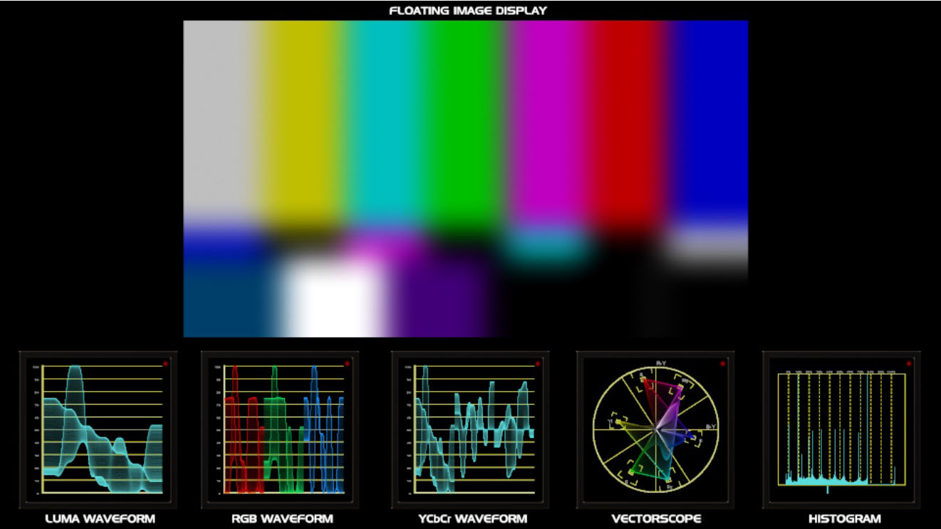
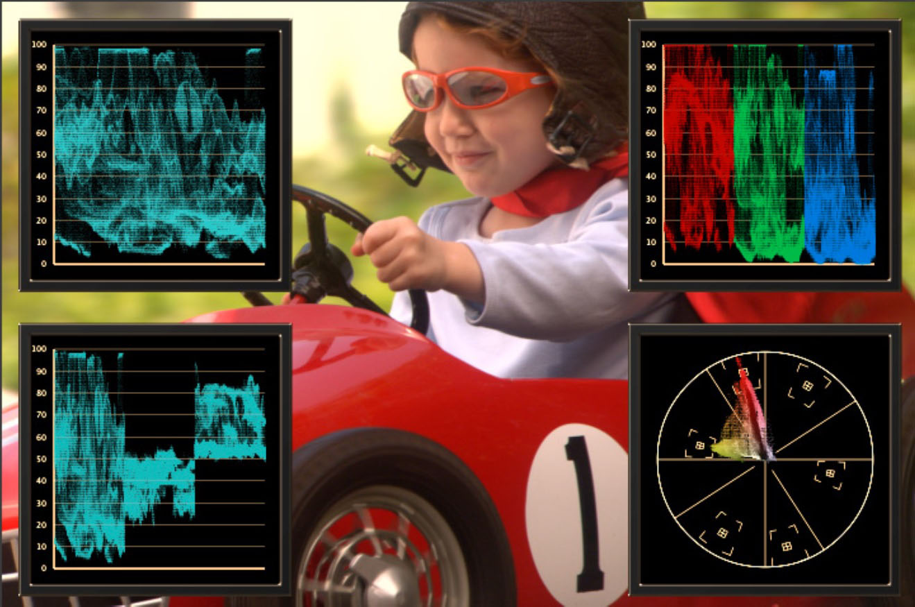
The input image can be displayed as a full frame background with the monitors positioned on top of the image, or it can be displayed as a floating image alongside the monitors. The floating image display can also be scaled to any size and positioned anywhere in the frame.
 |
The above image shows the input image displayed as a floating image, positioned at the center and top of the frame. Beneath the floating image and positioned along the bottom of the frame are, in order, the luma waveform monitor, the rgb waveform monitor, the ycbcr monitor, the vectorscope monitor and the histogram monitor displays.
Presets and Common Controls
BCC filters come with a library of factory installed presets plus the ability to create your own custom presets and preview them with the BCC FX Browser™.
BCC filters also include common controls that configure global effect preferences and other host-specific effect settings.
For more information about working with presets and other common controls, Click Here.
Preset Load/Save Mechanism Group
The preset load / save mechanism is located at the top of every filter in Boris Continuum.
Use the preset load save mechanism to load the factory installed or user generated animated and / or static presets for this filter or to save the current setting as a new animated or static preset.
Color Space pop-up: Used to instruct the filter of the sampling frequency that the input clip is using.
- SD – ITU.R BT 601 for standard definition video NTSC and PAL HD 720/1080 – ITU.R BT 709 for high definition (HD) video HD 1035 – SMPTE 240M for older Japanese broadcast video
Luminance Range pop-up: Used to set the scopes for full RGB video range of 0-‐255 or D1 video, which is clipped to 16-‐235.
- RGB (0 – 255)
- D1 (16 – 235)
Black Level at 7.5% IRE: This checkbox is used to set the waveform monitor black levels from 0 to 7.5 percent (7.5 IRE) for monitoring NTSC video in North America.
Sweep Field pop-up: The Videoscope filter can be set to monitor the full frame, only the upper field, or only the lower field from the input clip.
- Full – samples the full image frame
- Upper – samples only the upper field from the frame
- Lower – samples only the lower field from the frame
Sweep pop-up: The waveform beam can be set to sweep or scan the input horizontally or vertically
- Horizontal – waveform will scan the image horizontally
- Vertical – waveform will scan the image vertically
Units pop-up: The graticule overlay display used to measure the monitor waveform can be set to display in different units
- IRE – 0–100 intensity units (Institute of Radio Engineers)
- Volts – 0-0.7 voltage units
- RGB – 0–100 red, 0–100 green, 0-100 blue
Pixel Sampling pop-up: The Videoscope filter can be set to work with all of the pixels in the input image or a reduced set of pixels.
- Full – samples every pixel in the image
- Half – samples every other pixel in the image
- Quarter – samples every fourth pixel in the image
- Eighth – samples every eighth pixel in the image
Display Group
Contains parameters that control the appearance of the monitor displays.
Color Scheme White checkbox: Enable this option to set the videoscope monitors to display data in white instead of the standard green/blue color.
Background Opacity: The background of the monitors can be set to fully opaque, fully transparent or any level in between. Use this slider to set the level of opacity of the monitor background. At 100 percent the background is fully opaque and at 0 it is fully transparent.
Display Brightness: The brightness of data that is displayed in the monitors can be bright or dim. Use this slider to set the brightness of the display. At 100 the data is displayed at it’s brightest.
Monitor Brightness: The brightness of monitor bezel and the monitor display grid / graticule can be set to fully opaque, fully transparent or any value in between. Use this slider to set the opacity of the bezel and display grid. At 100 the monitor display is opaque is fully opaque and at 0 it is fully transparent.
Waveform Monitor Group
Contains options that control the Luma Waveform Monitor.
Waveform Monitor On checkbox: Enables the display of the Luma Waveform Monitor over the input clip.
Position: Used to set the position of the Luma Waveform Monitor over the input clip.
Scale: Used to set the size of the Luma Waveform Monitor.
Source Color checkbox: Used to set the color of the Luma Waveform Monitor.
RGB Waveform Monitor Group
Contains options that control the RGB Waveform Monitor.
RGB Waveform Monitor On checkbox: Enables the display of the RGB Waveform Monitor over the input clip.
Position: Used to set the position of the RGB Waveform Monitor over the input clip.
Scale: Used to set the size of the RGB Waveform Monitor.
Mode pop-up: Used to set the RGB data that the monitor is displaying:
- RGB: The Red, Green and Blue signals are displayed side-by-side
- R: Only the Red signal is displayed
- G: Only the Green signal is displayed
- B: Only the Blue signal is displayed
YCbCr Waveform Monitor Group
Contains options that control the YCbCr Waveform Monitor.
YCbCr Waveform Monitor On checkbox: Enables the display of the YCbCr Waveform Monitor over the input clip.
Position: Used to set the position of the YCbCr Waveform Monitor over the input clip.
Scale: Used to set the size of the YCbCr Waveform Monitor.
Mode pop-up: Used to set the data that the monitor is displaying:
- YCbCr Parade: The YCbCr signals are displayed side-by-side
- Cb: Only the Cb signal is displayed
- Cr: Only the Cr signal is displayed
Vectorscope Group
Contains options that control the Vectorscope display.
Vectorscope On checkbox: Enables the display of the Vectorscope over the input clip.
Position: Used to set the position of the Vectorscope Monitor over the input clip.
Scale: Used to set the size of the Vectorscope Monitor.
Calibration: Sets the Vectorscope to display either 75 percent amplitude (100 IRE equivalent) or 100 percent amplitude (130 IRE.)
- 75 Percent Color Bars – 100 IRE
- 100 Percent Color Bars – 130 IRE
Histogram Group
Contains options that control the Histogram.
Histogram On checkbox: Enables the display of the Histogram over the input clip.
Position: Used to set the position of the Histogram over the input clip.
Scale: Used to set the size of the Histogram.
Mode pop-up: Used to set the data that the monitor is displaying:
- Luma: The YCbCr signals are displayed side-by-side
- Red: Only the red signal is displayed
- Green: Only the green signal is displayed
- Blue: Only the blue signal is displayed
Zoom: Use to zoom into the Histogram, making it easier to read.
Floating Footage Group
Contains parameters that control the display of the filtered clip when it is set to float in the background unobscured by the scopes.
- Floating Position: Used to set the position of the floating image display.
- Footage Scale: Used to set the size of the floating image display.
- Render Over Black: This option renders the monitors along with the Floating Footage over a black background and is available only when the Floating Footage option is enabled.
Floating Footage Enable checkbox: Enables the displays of the filtered image clip in a separate floating window so that it can be viewed clearly, without obstruction, beside any enabled scope monitors over a black background.
Broadcast Safe Group
Contains parameters that are used to monitor broadcast color safe levels.
Logging Mode pop-up: The Logging Mode feature is used to control the output of the Videoscope filter. By default it is set to Render and Log, which means that the filter will render the enabled scope monitors onto the composite window and generate a scrollable text log when it encounters a frame in the timeline that includes chroma values that are out of gamut. The recorded log data is saved as a simple text file titled “videoscopelog.txt.” The filter does not automatically read through the timeline and only data from the current frame is included in the log. There are three options in this pop-up:
- Render and Log: Renders the monitor scopes into the frame and generates a text log when out of gamut values are encountered.
- Render Only: Only renders the scopes – no log is created.
- Log Only: Only generates a log – scopes are not rendered into the frame.
Working with Videoscope log files in Premiere
Premiere uses a predictive rendering scheme where it is constantly rendering multiple frames in the background in an effort to yield optimized preview speeds. Thus even when parked on a single frame in Premiere, the BCC Video Scope log file can generate entries for multiple framex when a render refreshes e.g. due to changing a parameter. The Video Scope log file entry for the current frame should be the first entry in the list if you clear the log file prior to forcing a render refresh.
Open Log File checkbox: When clicked, opens the color safe log file, which contains time and frame stamps for frames that contain values that are outside of the broadcast color safe settings.
Highlight On Scope checkbox: When enabled, renders a warning color over the scopes highlighting out of range values.
Highlight On Source checkbox: Contains the following render options for the out of range display:
- Off: The feature is disabled and no color or pattern is added.
- Zebra Pattern: Renders a striped zebra pattern over the image and scopes highlighting out of range values
- Magenta: Renders a magenta color over the image and scopes highlighting out of range values.
Luma Upper Threshold: Used to determine what luma values the filter will consider to be out of gamut. When an out of gamut value is encountered, a red light will appear in the top right portion of each monitor.
Luma Lower Threshold: Used to determine what luma values the filter will consider to be out of gamut. When an out of gamut value is encountered, a red light will appear in the top right portion of each monitor.
Chroma Threshold: Used to determine what chroma values the filter will consider to be out of gamut. When an out of gamut value is encountered, a red light will appear in the top right portion of each monitor.


