


- Introduction
- New in Mocha Pro 2026.5
- Interface Overview
- Stereo Interface
- Using the Mocha Pro Plugins
- Applying the Mocha Plugin for Adobe After Effects
- Applying the Mocha Plugin for Adobe Premiere
- Applying the Mocha Plugin for Avid Media Composer
- Applying the Mocha OFX Plugin
- Adding the Mocha Plugin inside Autodesk Flame
- Adding the Mocha Plugin inside Blackmagic Design Fusion Studio
- Adding the Mocha Plugin inside The Foundry Nuke
- Adding the Mocha Plugin inside Silhouette
- Adding the Mocha Plugin inside Vegas Pro
- Basic workflow for the Mocha OFX Plugin
- Using the Mocha GUI
- Controlling Mattes
- Controlling Module Renders
- Rendering Insert Layers
- Dealing with Alpha Channel Input and Output
- Applying the Mocha HitFilm or Mocha Pro Plugin inside HitFilm
- 360 VR and Stereo Views Workflow
- Loading Projects containing the Mocha VR Plugin
- Starting a New Project
- Workflow inside Mocha
- Creating a New Project in the Mocha Standalone application
- Setting Up a New Project For VR 360
- Setting Up a New Project For Stereo
- Creating a New Project in the Mocha Pro Plugin
- Creating a New Project in the BCC 10 Mocha PixelChooser
- Setting the In and Out Points
- Project Frame Offsets and Clip Frame Offsets
- Tips for New Projects
- Merging and Importing Projects
- Tracking Basics
- The Planar Tracker
- The Relationship Between Splines and Tracking Data
- Selecting an Area to Track
- Dealing With Obstructions or Reflective Surfaces
- Tracking Parameters
- Tracking the Spline
- Checking Your Track
- Redoing or Deleting Tracking Keyframes
- Importing Mattes
- Merging Tracks
- Keyframe Controls
- Tips for Tracking
- PowerMesh and Mesh Tracking
- Face Detection
- Stereo Tracking
- AdjustTrack
- AdjustTrack Classic
- Starting the Track Adjustment
- Reference Points
- Reference Point Quality
- AdjustTrack with More than Four Reference Points
- Working Backwards
- About Primary Reference Points (the red X)
- Changing the Primary Frame for a Reference Point
- Selecting Different Reference Points
- Deleting Reference Points
- Nudging Reference Points
- View Options
- Tips for AdjustTrack
- Rotoscoping Basics
- The Art of Rotoscoping
- Mocha Tracking and Roto
- Inserting Points
- Removing Points
- What’s the Überkey?
- Translate, Rotate and Scale your Splines
- Turning On and Off Points
- Add Motion Blur
- Changing the Matte Blend Mode
- Viewing your Mattes
- Changing the Background Color
- Colorize your Matte Overlay
- Hiding splines or points
- Preview Rendered Mattes
- Open Splines
- Using Falloff for Adjusting Larger Clusters of Points
- Splitting Contours into Different Layers
- Snapshot Duplicates
- Displaying spline contours for a single frame
- Compositing a Group of Layers
- Tips for Rotoscoping
- Rotoscoping with Magnetic and Freehand Tools
- Painting Splines with the Area Brush Tool
- Creating Mattes with Machine Learning Tools
- Stereo Rotoscoping
- The Export Data Dialog
- Exporting Tracks
- Exporting Tracks to Adobe After Effects
- Exporting Tracks to Silhouette
- Exporting tracks to Mistika
- Exporting Tracks to Nuke
- Exporting Tracks to Blackmagic Fusion
- Exporting Tracks to Inferno, Flame, Flint, Smoke and Combustion
- Exporting Tracks to Assimilate SCRATCH
- Exporting Tracks to SGO Mistika
- Exporting Tracks to HitFilm
- Exporting 2D Alembic Data
- Exporting 2D Tracking Data to SynthEyes
- Exporting Stereo Tracking Data
- Legacy Track Data Formats
- Exporting Mattes and Clips
- Exporting Rendered Shapes
- Exporting Matte Colors as Transparent Channels
- Exporting Stereo Rendered shapes
- Exporting as Adobe After Effects Mask Data
- Exporting Adobe Premiere Pro CC Masks
- Exporting Flame Gmask and Flame Gmask Tracer data
- Exporting Shapes to HitFilm
- Exporting Roto, RotoPaint and SplineWarp Nodes to Nuke
- Exporting Shape Data to Blackmagic Fusion Shapes
- Exporting Shape Data to Silhouette Shapes
- Legacy Shape Data Formats
- Exporting Stereo Shape Data
- Exporting Rendered Clips (Mocha Pro)
- Exporting Stereo Rendered Clips
- The Camera Solve Module
- Overview
- The Camera Solve Workflow
- Camera Solve Parameters
- Features? Blips? Trackers? What are you talking about?
- Average Error - The Solve Quality
- Solving 3D Moving Objects
- Object Projection
- Navigating the 3D Viewer
- 3D Objects and Properties
- 3D Alignment
- Importing Models
- Measuring Distance
- Exporting Camera Solves
- Exporting Camera Data Process
- Exporting to SynthEyes Projects
- Importing Mocha 3D Data to Compositors
- The Insert Module
- The Mega Plate Module
- Using Mega Clean Plates in the Remove Module
- The Remove Module
- The Stabilize Module
- The Lens Module
- Overview
- Lens Workflow with Line Detection Calibration
- Lens Workflow with Layer Splines
- Equirectangular Lens Workflow with 360 VR
- Lens Parameters
- Exporting
- Rendering lens distortion
- Using Grid Images
- Anamorphic Camera Model
- Calibrating the Image Center
- Manual calibration
- Lens Workflow with Distortion Maps
- Exporting Lens Data [Mocha Pro Only]
- Tips for Lens Calibration
- Using Mocha Pro for 360 VR workflow
- The Reorient Module
- Graphs
- The Clip Module
- Keyboard Shortcuts
- Preferences
- OpenColorIO (OCIO) Color Management
- OCIO Color Management
- A Brief Overview of Color Management
- Mocha in the Color Pipeline
- Setting the Working Color Space
- Setting the Display View color space
- Defining the Clip Color Space
- Defining the Overall Project Color Space
- Loading OpenColorIO configurations into Mocha
- Mocha Pro OCIO inside Plugin versions
- Setting Defaults for Color Space Workflow
- File Formats
- Command Line
- Environment Variables
- Installing Node-Locked Licenses
- Installing Floating Licenses
- Installing Render Licenses
- Troubleshooting Mocha issues
- Third Party Open Source and Commercial Licenses Used by Mocha
Introduction
Welcome to Mocha, tracking and rotoscoping tools that make your tracking and rotoscoping work much easier.
Our tools are based on our proprietary Planar Tracking technology, an awesome approach to 2D tracking which will help you to generate accurate corner-pins and track and transform your roto splines in a powerful way.
The Art of Tracking
Tracking and rotoscoping are part of almost any visual effects project. For 2D tracking, point trackers are most commonly used, but to get good point tracks requires a mix of experience and luck. You often have to "prime" a clip for optimum tracking using color correctors and other image manipulations. If the point being tracked exits frame, you get into offset tracking, which presents its own set of challenges. If it all fails, you are into hand tracking, which is time consuming and very hard to get accurate.
Mocha is a 2D tracker that requires less experience and luck to be successful with, does not require the image to be primed and is less likely to require a lot of tricks or hand tracking on difficult shots.
A Planar Approach to Surface Tracking
In Mocha splines are used for both tracking and rotoscoping. This is a different method from standard 1-point or multi-point tracking tools.
Traditional tracking tools require that you locate "points" that remain consistent throughout the entire shot in order to track movement.
This is itself a difficult task, especially when tracking a shot that was not originally designed to be tracked.
If you wish to also track rotation, perspective and shear you need even more clear and consistent points to track.
Traditional roto methodology would have you outline a shape with the minimum number of points necessary then either manually move the control
points or track the shape with a point tracker to "get it close". Even when using multi-point trackers to impart rotation and scale to the roto spline,
the results are often unusable if there is any perspective change during the shot.
Instead, Boris FX’s Planar Tracker tracks an object’s translation, rotation and scaling data based on the movement of a user-defined plane.
A plane is any flat surface having only two dimensions, such as a table top, a wall, or a television screen. Planes provide much more detail to the
computer about an object’s translation, rotation and scaling than is possible with point-based tracking tools. Even as an object leaves and enters a frame,
there is usually enough information for the Planar Tracker to maintain a solid track of the object.
When you work with the Mocha tools, you will need to look for planes in the clip. More specifically, you will need to look for planes that coincide with
movements you want to track. If someone is waving goodbye, you can break their arm into two planes - the upper and lower limbs.
Although not all of the points on the arm sections actually lie on the same two-dimensional surface, the apparent parallax will be minimal.
The World Isn’t Flat
Controversial, I know.
Because the world is not all made up of planes, we also have other tracking tools to help with that.
With the addition of PowerMesh in Mocha Pro, sub-planar tracking is also possible, tracking warp and bending of objects that standard planar tracking would struggle to do alone.
In Mocha Pro 2026.5 we introduced the option to use Point Track ML, a significant improvement for PowerMesh tracking and AdjustTrack nudging.
Combining these tools together you can generate 3D meshes and cameras to get depth using the Camera Solve Module.
While the core of Mocha tracking is still planar, these new tools help solve difficult tracking problems where one pass of tracking is not enough.
New in Mocha Pro 2026.5
Object Brush Auto ROI
Get more accurate object masks by setting a smaller region
Automatically define the area to mask just by clicking with the object brush
Turn off Auto ROI and Ctrl/CMD drag with the object brush to define your own area to mask within.
See Creating Mattes with Machine Learning Tools for more details.
Matte Assist Search Area
Get more accurate Matte Assist ML mattes by defining the search area around your mask. See Creating Mattes with Machine Learning Tools for more details.
Matte Refine Auto ROI
More accurate, refined mattes and fewer artefacts by defining the region around your spline. See Creating Mattes with Machine Learning Tools for more details.
PowerMesh with Point Track ML
Use machine learning to better place mesh points during the track.
Better tracking for light changes, turning or obscured surfaces and points that go off screen
Additional refinement mode for more accurate placement
See PowerMesh and Mesh Tracking for more details.
Planar from Mesh Track
Fit the planar track to the mesh track
Supports better control of the surface where the mesh track is used on turning surfaces
AdjustTrack with Point Track ML
Use machine learning to more accurately nudge points in difficult tracking scenarios
Use Auto nudge to handle spaced nudging across the timeline as a first pass
Additional refinement modes: Per-point options for slower but more accurate placement, and Image for faster refinement
Even further refinement options for tricky shots using support grids. Use additional grids of points to help find the right position, even when off-screen.
See AdjustTrack for more details.
New Matte Export Options
Export Rendered Mattes to Alpha: You can now render RGBA mattes to disk that include the RGB clip with the matte as an alpha. Previously, you could only render the mattes separately.
Export Rendered Mattes to Multi-layer EXR: You can now render all layer mattes to separate channels using multi-layer EXR files.
Export Rendered Mattes to Color-Blended Overlays: Mattes can be rendered as their layer colors, cross blending any colors that overlap each other.
See Exporting Rendered Shapes for more details on the new export render options.
Updated Curve Editor
Curve editor can now display PowerMesh vertex positions, making it easier to see problems in the track.
Updated Python API
More granular access to PowerMesh properties
Add and remove vertices in a PowerMesh
Access Matte Assist contours just like regular layer contours
Functions to render Matte Assist layers
See the separate Python Guide and Reference for more details.
Smaller Changes
Mocha will now show a different progress indicator when a tool is initialising or needs to take a while to process something.
The Mocha Pro logo has been updated to match the overal Boris FX product lineup.
Mocha Pro now supports Windows on ARM.
Improved Refine Mattes memory handling
Refine Matte options can now be keyframed
Python Script editor font size is now consistent with system settings
Interlaced Rendering for ML Mattes: Machine Learning based mattes now support interlaced projects when rendering back to the host.
Interface Overview
To quickly get familiar with Mocha before you dive into the rest of the manual, here is a breakdown of the interface and its controls.
| Some parts of the Interface Overview uses the Mocha Pro Interface. Versions of the Mocha Pro Plugin, Mocha HitFilm, Mocha for After Effects etc. may differ in presentation, but their tools perform the same function |
Layouts
Mocha layouts are modifiable, allowing you to hide or reveal many parts of the interface.

These layouts are clustered into 4 default types you can build from.
Essentials Layout
Mocha begins in the Essentials layout, which provides a simplified interface for basic tracking and roto.

The basic toolbar provides a minimal set of tools without cluttering the interface.
The Essentials panel on the left side of the window combines everything you need for a basic track and mask.
Clicking one of the top buttons, Track or Mask, shifts Mocha into a set of tracking or Masking operations.
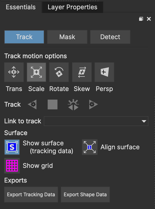
Track Panel
The Track Panel contains the following features (from top to bottom):
Track Motion Options
The 5 motion types you can track in:
Translation
Scale
Rotation
Shear (sometimes known as Skew)
Perspective
Track Buttons
For tracking backwards, forwards and to stop the track
Link to Track
To attach a spline layer to an existing track, or detach it from a track entirely.
See Tracking Basics and Rotoscoping Basics for more information on the benefits of Link to Track.
Surface
These buttons control viewing and expanding the surface.
See Tracking Basics for how to use the surface effectively.
Show surface (tracking data): Reveals the blue surface that represents the tracking data.
Show grid: Reveals a useful grid for lining up the surface or monitoring for drift in a track.
Align surface: Expands the surface to fit the dimensions of the footage on the current frame.
Mask Panel
The Mask panel has options for a series of tools featured in the Matte module, specifically around Matte Assist ML.
We recommend reading the section called Creating Mattes with Machine Learning Tools for how to use these tools.

Matte Assist ML Options
Generate Object Matte: A toggle button to turn on the Matte Assist ML for a selected layer
Dilate Matte: A field to increase or decrease the Matte out from the original edge. This includes a "Render on change" button to see the dilation changes as you modify the value.
Render Options: Render backwards, render current frame, render back and forth and render forwards for generating the Matte Assist ML matte across your timeline.
Composite Layers in Group: This option lets you combine multiple layers in a group and treat them as a single matte. See the Rotoscoping Basics section for more on this workflow.
Detect Panel
The Detect panel has tracking options for detecting Faces in the shot.
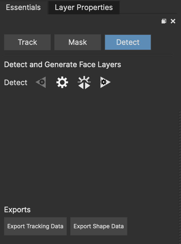
Render Options for generating ellipses for any faces detected in the shot:
Detect Faces Backwards
Detect Faces in Current Frame
Detect Back and Forth
Detect Faces Forwards
We recommend looking at the Face Detection section for how to use the Face Detection tool.
Exports
The exports appear on both the Track and Mask panels and open the Export dialog. See The Export Data Dialog for more details.
Classic Layout
For Mocha veterans, the Classic layout is arranged like the original Mocha.
Use this mode if you are familiar with Mocha and want access to all the parameters and tools.
Roto Layout
Like the Essentials layout, this layout is optimized specifically for roto sessions where only the most necessary panels and tools are shown.
Big Picture Layout
If you want to reduce all clutter entirely, the Big Picture layout is very useful for previewing shots without any elements getting in the way.
Saving Custom Layouts
You can add or remove many parts of the Mocha interface, such as:
Timeline controls
Toolbars
View controls
Etc.
These can either be access by right clicking the area of the interface and choosing a GUI element to show or hide, or selecting from the View menu.
Any changes you make to a layout will not be saved unless you choose View | Layout | Save Current Layout.
For example if you like the Essentials layout, but would like the Advanced toolbar from the Classic layout:
Choose "Essentials" from the layout drop-down
Choose "Advanced Tools" from
View | ToolbarsChoose
View | Layout | Save Current layout
This will now save the Essentials layout with the new toolbar.
Alternatively, you can save the layout as a new custom layout:
Make changes to your existing layout
Choose
View | Layout | Save Current layout as…Enter the new name in the Manage Custom Layouts dialog
You can add, order or remove layouts from the Manage Custom Layouts dialog in the same sub-menu.
Any new layout will automatically be assigned a Ctrl/CMD + Number shortcut based on the order of the layouts, up to 9.
If you have made changes to a saved layout want to revert back to the saved version, just choose View | Layout | Revert to saved.
If you want to revert back to the original default layout, just choose View | Layout | Revert to default.
The Advanced Toolbar

At the very top of the interface you have the tools that form the brunt of your time inside Mocha.
| Save Project: Save the project |
| Select: Selection tool for splines and points. Hold the button to choose between Marquee selection and Lasso selection. |
| Select Both: Selects both the Inner spline points and the edge points. Hold this button down to select further options (See below) |
| Select Inner: Only selects the inner spline points |
| Select Edge: Only selects the outer edge points |
| Select Auto: Automatically selects between Inner and Edge points |
| Add Point: Tool to add points to the spline. You can also hold down the CMD/Ctrl key while using the Selection/Pick tool. |
| Pan: Used to pan the footage in the Viewer |
| Zoom: Used to zoom into footage in the viewer |
| Create X-Spline Layer: Draw a new X-Spline layer |
| Add X-Spline to Layer: Draw an X-spline that is added to the current spline layer. |
| Create Bezier-Spline Layer: Draw a new B-Spline layer |
| Add Bezier-Spline to Layer: Draw a B-spline that is added to the current spline layer. |
| Create New Magnetic Layer: Draw a magnetic line that converts to an X-Spline. |
| Add Magnetic Shape Selected to Layer: Add a new magnetic line that converts to an X-Spline in the existing layer. |
| Create New Freehand Layer: Draw a freehand line that converts to an X-Spline. |
| Add Freehand Shape Selected to Layer: Add a new freehand line that converts to an X-Spline in the existing layer. |
| Create Mask ML Object Brush Layer: Automatically matte selected objects on the canvas to convert into a single-frame spline. |
| Add Mask ML Object Brush Spline to Layer: Automatically matte selected objects on the canvas to add new spline contours to existing layers. |
| Create Area Brush Layer: Paint on the canvas to generate an X-Spline. |
| Add Area Brush to Layer: Paint on the canvas to add an X-Spline to an existing layer. |
| Create Rectangle X-Spline Layer: Draw a new Rectangle X-Spline layer. Double-click to create a rectangle in the middle of the view. |
| Add Rectangle X-Spline to Layer: Draw an Rectangle X-spline that is added to the current spline layer. Double-click to create a rectangle in the middle of the view. |
| Create Rectangle Bezier-Spline Layer: Draw a new Rectangle B-Spline layer. Double-click to create a rectangle in the middle of the view. |
| Add Rectangle Bezier-Spline to Layer: Draw a Rectangle B-spline that is added to the current spline layer. Double-click to create a rectangle in the middle of the view. |
| Create Ellipse X-Spline Layer: Draw a new Ellipse X-Spline layer. Double-click to create an Ellipse in the middle of the view. |
| Add Ellipse X-Spline to Layer: Draw an Ellipse X-spline that is added to the current spline layer. Double-click to create an Ellipse in the middle of the view. |
| Create Ellipse Bezier-Spline Layer: Draw a new Ellipse B-Spline layer. Double-click to create an Ellipse in the middle of the view. |
| Add Ellipse Bezier-Spline to Layer: Draw a Ellipse B-spline that is added to the current spline layer. Double-click to create an Ellipse in the middle of the view. |
| Attach Layer: Used to select a point and drag-lock it to another layer spline point. Useful for lining up individual splines. |
| Rotate: Rotate selection around the axis of the point you click in the viewer |
| Scale: Scale Selection |
| Move: Move selection |
| EditMesh: Toggles layer into Edit Mesh Mode for editing mesh vertices. |
| Transform Tool: Toggles the transform bounding box for manipulating selections |
| Show Planar Surface: Toggles the planar surface view |
| Show Planar Grid: Toggles a grid relative to the planar surface view. You can adjust the number of grid lines under Viewer Preferences (See below) |
| Align Surface: Expands the layer surface to fit the dimensions of the footage at the current frame. All tracked data is made relative to this new alignment. |
| Add Vertex: Adds a vertex to a selected edge when in Edit Mesh Mode. |
| Selection Falloff: Toggles the radial selection falloff for the current point. Works for spline points and mesh points (when in Edit Mesh mode). |
| Measure Distance: Turns on the distance measurement tool for 3D solved features in the Camera Solve module. |


Basic Toolbar

In Essentials Mode, only a basic set of these tools is shown, to simplify the interface.
| Save Project: Save the project |
| Select: Selection tool for splines and points. Hold the button to choose between Marquee selection and Lasso selection. |
| Add Point: Tool to add points to the spline |
| Pan: Used to pan the footage in the Viewer |
| Zoom: Used to zoom into footage in the viewer |
| Create X-Spline Layer: Draw a new X-Spline layer |
| Add X-Spline to Layer: Draw an X-spline that is added to the current spline layer. |
| Create Bezier-Spline Layer: Draw a new B-Spline layer |
| Add Bezier-Spline to Layer: Draw a B-spline that is added to the current spline layer. |
| Create New Magnetic Layer: Draw a magnetic line that converts to an X-Spline. |
| Add Magnetic Shape Selected to Layer: Add a new magnetic line that converts to an X-Spline in the existing layer. |
| Create New Freehand Layer: Draw a freehand line that converts to an X-Spline. |
| Add Freehand Shape Selected to Layer: Add a new freehand line that converts to an X-Spline in the existing layer. |
| Create Mask ML Object Brush Layer: Automatically matte selected objects on the canvas to convert into a single-frame spline. |
| Add Mask ML Object Brush Spline to Layer: Automatically matte selected objects on the canvas to add new spline contours to existing layers. |
| Create Area Brush Layer: Paint on the canvas to generate an X-Spline. |
| Add Area Brush to Layer: Paint on the canvas to add an X-Spline to an existing layer. |
| Create Rectangle X-Spline Layer: Draw a new Rectangle X-Spline layer. Double-click to create a rectangle in the middle of the view. |
| Add Rectangle X-Spline to Layer: Draw an Rectangle X-spline that is added to the current spline layer. Double-click to create a rectangle in the middle of the view. |
| Create Rectangle Bezier-Spline Layer: Draw a new Rectangle B-Spline layer. Double-click to create a rectangle in the middle of the view. |
| Add Rectangle Bezier-Spline to Layer: Draw an Ellipse B-spline that is added to the current spline layer. Double-click to create an Ellipse in the middle of the view. |
| Create Ellipse X-Spline Layer: Draw a new Ellipse X-Spline layer. Double-click to create an Ellipse in the middle of the view. |
| Add Ellipse X-Spline to Layer: Draw an Ellipse X-spline that is added to the current spline layer. Double-click to create an Ellipse in the middle of the view. |
| Create Ellipse Bezier-Spline Layer: Draw a new Ellipse B-Spline layer. Double-click to create an Ellipse in the middle of the view. |
| Add Ellipse Bezier-Spline to Layer: Draw a Ellipse B-spline that is added to the current spline layer. Double-click to create an Ellipse in the middle of the view. |
| Show Planar Surface: Toggles the planar surface view |
| Show Planar Grid: Toggles a grid relative to the planar surface view. You can adjust the number of grid lines under Viewer Preferences (See below) |
| Align Surface: Expands the layer surface to fit the dimensions of the footage at the current frame. All tracked data is made relative to this new alignment. |
See descriptions in Advanced Toolbar above for the rest of the tools.
The Viewer Controls

These controls cover what can been seen or hidden while working in the Mocha viewer.
| The Viewer controls are turned off in some layouts. You can turn them on via the View menu. |
| Clip to Show: Choose which clip to view from this dropdown |
| Proxy Scale: Adjust the resolution of the footage for performance (Mocha Standalone only) |
| Show RGB Channels: Turns on the RGB view of the footage. Select from the dropdown to choose an individual color channel to view. |
| Show Alpha Channels: Turns on the Alpha view of the footage |
| Show Layer Mattes: Toggle on or off to show the mattes. Select from the dropdown to choose the type of matte |
| Color Layer Mattes: Fills matte with Color. Decreasing the value lessens the opacity |
| Overlays: Toggles all viewer overlays, including splines, tangents, surface and grid |
| Show Layer Outlines: Toggles all spline overlays, including splines, points and tangents |
| Show Spline Tangents: Toggles spline tangents view. Select from the dropdown to choose the type of view |
| View Mesh: Toggles Mesh view. Select from the dropdown to choose either the mesh or just the vertices. |
| Show Zoom Window: Toggles the Zoom window |
| Stabilize: Turns on Quick Stabilize Preview. This centers the footage around your tracked surface using the tracking data linked to pan and zoom. You can choose different layers to stabilize the viewer from the dropdown in the button. |
| Trace: Turns on the traced path of the tracked surface. You can adjust the amount of frames to trace under Viewer Preferences (See below) |
| Enable Brightness/Gamma Scaling: Toggles non-destructive brightness and gamma adjustment to work with low-contrast footage. The left field adjusts brightness, the right field adjusts gamma. |
| Toggle 3D View: Toggles the 3D view for solved Cameras from the Camera Solve module. Holding down the button will reveal the different 3D views available. |
| Toggle 3D Ground Plane: Toggles the ground plane for 3D views in the Camera Solve module. Holding down the button will reveal the different 3D views available. |
| Toggle 3D View: Toggles the footage background for solved Cameras in the Camera Solve module. |
| Toggle Texture View: Toggles the texture for solved meshes in the Camera Solve module. |
| Viewer Preferences: Adjustments dialog for parameters such as grid lines and trace frames. Also controls for viewer OCIO colourspaces. |


The Timeline Controls

The timeline controls cover frame range, playback, tracking controls and key-framing.
| Some timeline controls may not be visible in certain layouts. You can turn them on via the View menu or by right-clicking the timeline. |
| Project In-Point: Frame where timeline playback starts |
| Set In-Point: Set the in-point for the timeline |
| Reset In-Point: Set the in-point back to the start of the clip |
| Current Frame: The frame the playhead is currently on. Enter a new value to jump to that frame. |
| Reset Out Point: Set the out point back to the end of the clip |
| Set Out Point: Set the out point for the timeline |
| Project Out Point: Frame where timeline playback ends |
| Zoom Timeline to In/Out points: Expands the timeline between the in and out points to the edges of the viewer. This will toggle to the Full range button below. |
| Zoom Timeline to full frame range: Resets the timeline scale to the full range of frames. This will toggle to the In/Out range button above. |
| Play Controls: Controls for playing back and forth and moving one frame at a time. |
| Change Playback Mode: Toggles tri-state button between Play once, Loop and Bounce playback modes. |
| Tracking Controls: Controls for tracking back and forth and tracking one frame at a time. |
| Go to Previous Keyframe: Jump to the previous keyframe set in the timeline for that layer |
| Go to Next Keyframe: Jump to the next keyframe set in the timeline for that layer |
| Add New Keyframe: Add a new keyframe at the current position for the selected layer. This only appears if you are not hovering over an existing keyframe. |
| Delete New Keyframe: Deletes the keyframe at the current position for the selected layer. This only appears if you are hovering over a keyframe. |
| Delete All Keyframes: Deletes all keyframes on the timeline for the selected layer |
| Delete All Forward Keyframes: Deletes all keyframes on the timeline forward from the playhead for the selected layer |
| Delete All Backward Keyframes: Deletes all keyframes on the timeline backward from the playhead for the selected layer |
| Autokey: Toggles automatic key insertion when moving points or adjusting parameters |
| Überkey: Toggles the Überkey, which modifies all keys in the layer relative to the key you are now on. |


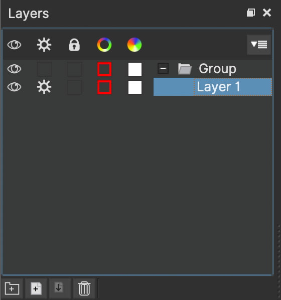
Layer Controls
The top left hand panel contains the tools to manage layers.
| Layer Icons:
|
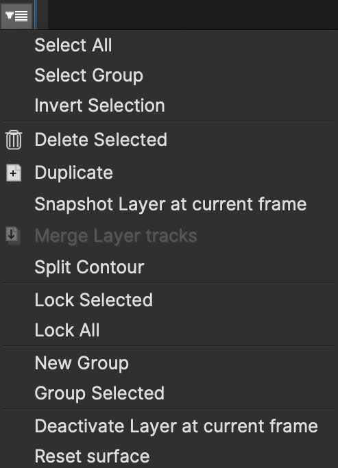
| Layer Actions dropdown:
|
| Group Layer: Groups the currently selected layers. If no layers are selected, creates an empty group. |
| Duplicate Layer: Duplicates the currently selected layers |
| Merge Layers: Merges the selected layers' tracks to a new layer |
| Delete Layer: Delete currently selected layers on all frames |


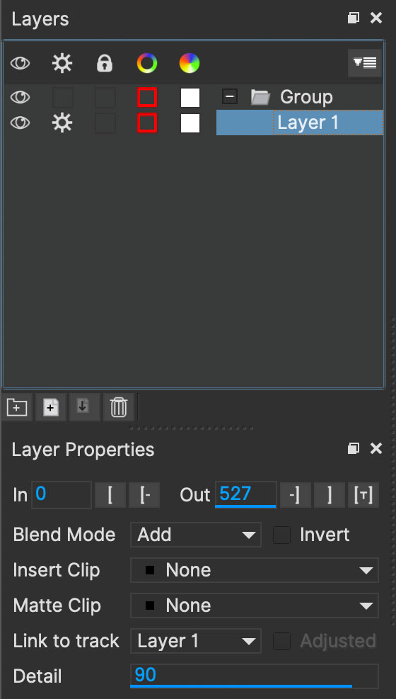
Layer Properties
The section under the Layer Controls panel contains the properties for each layer.

Layer In/Out frames: Settings to change where the layer turns on and off in the clip
Set In/Out to Tracked Region: Sets the in/out range of the layer to the tracked frames
Blend mode: Dropdown to add or subtract your spline to the current layer. Invert flips this
Insert Clip: Insert a demo clip to preview your track. You can use one of the defaults or import your own. For preview purposes only
Matte Clip: Replaces the current layer splines with a matte clip.
Link to Track: Which layer track to link your layer splines to. Can also be set to None. You can select multiple layers before choosing this option.
Link to adjusted track: Optional checkbox to link the layer splines to the adjusted track of the selection in "Link to Track"
Detail: Used to adjust the amount of points in a magnetic or freehand spline.
Cache Management
In Mocha v5 we introduced manual cache clearing to allow you to clear the Mocha cache at the project, render or global level.
You can access the Clear Cache option from the file menu under File → Clear Cache…

You can check the following options:
Project Cache: Clear the cache for the currently loaded project
Rendered Clips: Clear just the rendered clips for the project
Global Cache: Clear everything in the entire Mocha cache.
Only clear the Global Cache if you are certain you don’t want any of your existing project caches to remain.
| Whenever you close the Mocha Plugin GUI, any renders you perform are cleared in order to make sure that you get a reliable render in the host. If you want to keep a render you have completed inside Mocha, it is important that you export it first from the File menu. If you want to learn more about this, see the File and Clip section of Troubleshooting Mocha issues. |
Stereo Interface
Some interface elements change when using Stereo footage. This section covers what new icons appear and how to interact with them.
Viewing in Stereo
In stereo mode you will see 3 buttons in the View Controls next to the clip view drop down on the left:
Two buttons to show individual Left or Right views (L and R). These button names change according to the abbreviation you assign them in Project Settings.
A 3D button to preview stereo views
You can preview stereo work at any time by turning on the 3D button in the view controls.
![]()
Clicking and holding on the 3D button will give you a range of stereo view options.
Interlaced: Each view is show on every other line in fields
Active: If you have an active shutter monitor available, you can view in this mode (Note: Only tested on Windows)
Anaglyph: Probably the most common mode to view stereo work through. You can choose from Red/Cyan or Green/Magenta
Difference: A difference mode of the views laid over each other. This view also has additional functionality explained below
Timeline Controls in Stereo
Two new icons appear in the timeline to assist with tracking and roto in stereo:
| Track/Render on All Views: Toggle this button in the timeline to Track/Render in both eyes |
| Keyframe on All Views: Toggle this button in the timeline to maniuplate keyframes in both eyes |


Both these buttons and their uses are covered in the Stereo Tracking and Stereo Roto sections of the User Guide.
Using the Mocha Pro Plugins
| In Mocha Pro 2019 and above, the Mocha VR plugin is as a legacy plugin. This is because all Mocha VR features are now inside Mocha Pro. The Mocha VR category is maintained for compatibility with Mocha VR V5 plugin projects. |
The Mocha Pro plugins are separate from the standalone Mocha and can be applied as an effect directly onto layers in host applications.
This reduces the need to swap out of your host application and streamlines getting data in and out of Mocha.
The biggest advantage is you can set up layers and module settings in Mocha as normal, and then have the results render directly to the host timeline without having to export.
| The guides below are using examples of the Mocha Pro plugin. For more information on using the 360 Features in the Mocha Pro Plugin, see Using Mocha for 360 workflow |
Applying the Mocha Plugin for Adobe After Effects
The Mocha Pro Plugin for Adobe appears in the Effects menu like every other effect.
Simply apply the effect to the layer you want to work with.
The general workflow for the Mocha Adobe Plugin is as follows:
Select any additional source layers you want to use inside Mocha
Launch Mocha. This will load a full version of the Mocha interface that you can use just like the standalone version.
Use Mocha as required and then close and save. No rendering is required inside Mocha unless you want to.
Choose whether you want to use mattes, renders or any other data from Mocha back in the plugin interface.
Using the Mocha GUI
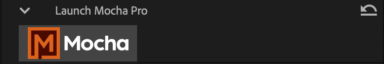
Once you have applied the Mocha Pro effect, you can click on the Mocha button to launch the main interface.

This then becomes exactly like working in the standalone version of Mocha, with a few exceptions.
First, you will notice you don’t need to set up a project like in the standalone version. The source layer is automatically loaded and ready to track in the view.
Secondly you don’t need to save out a project file (unless you want to export it). You just close and save the Mocha view when done and the project is saved inside the Effect like any other Adobe effect.
By default, the starting timeline frame will always be zero, which will not affect your data generation back in After Effects.
For users using timecodes instead of frame numbers in After Effects, the correct timecode offset will display inside the Mocha GUI.
For further details on how to use anything inside the Mocha GUI, see the rest of the User Guide!
| The Mocha Pro Plugin interface is almost exactly the same as the standalone interface, so most of the usual guide and video tutorials can be applied to the plugin. |
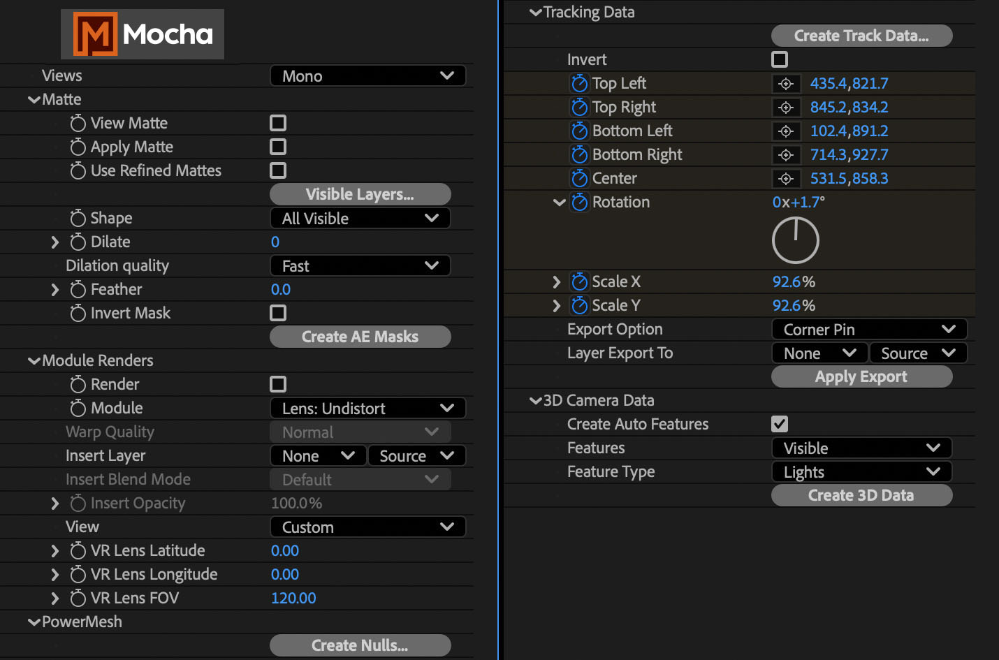
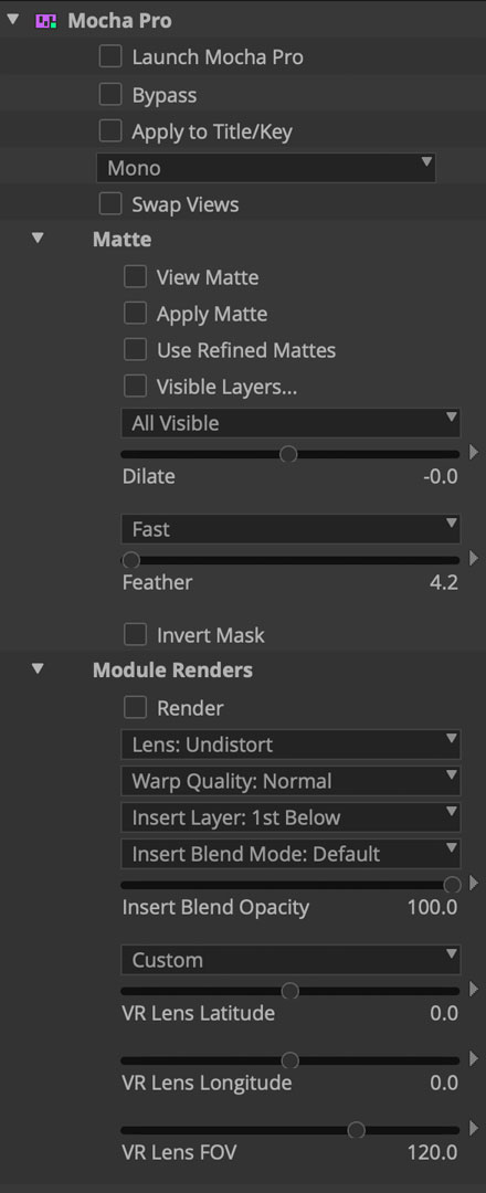
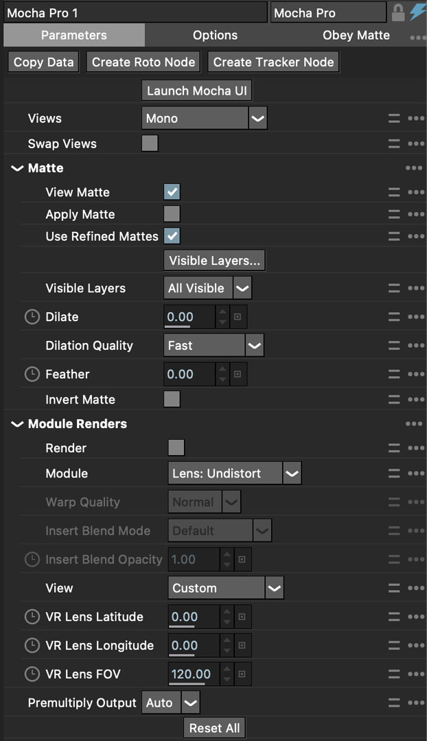
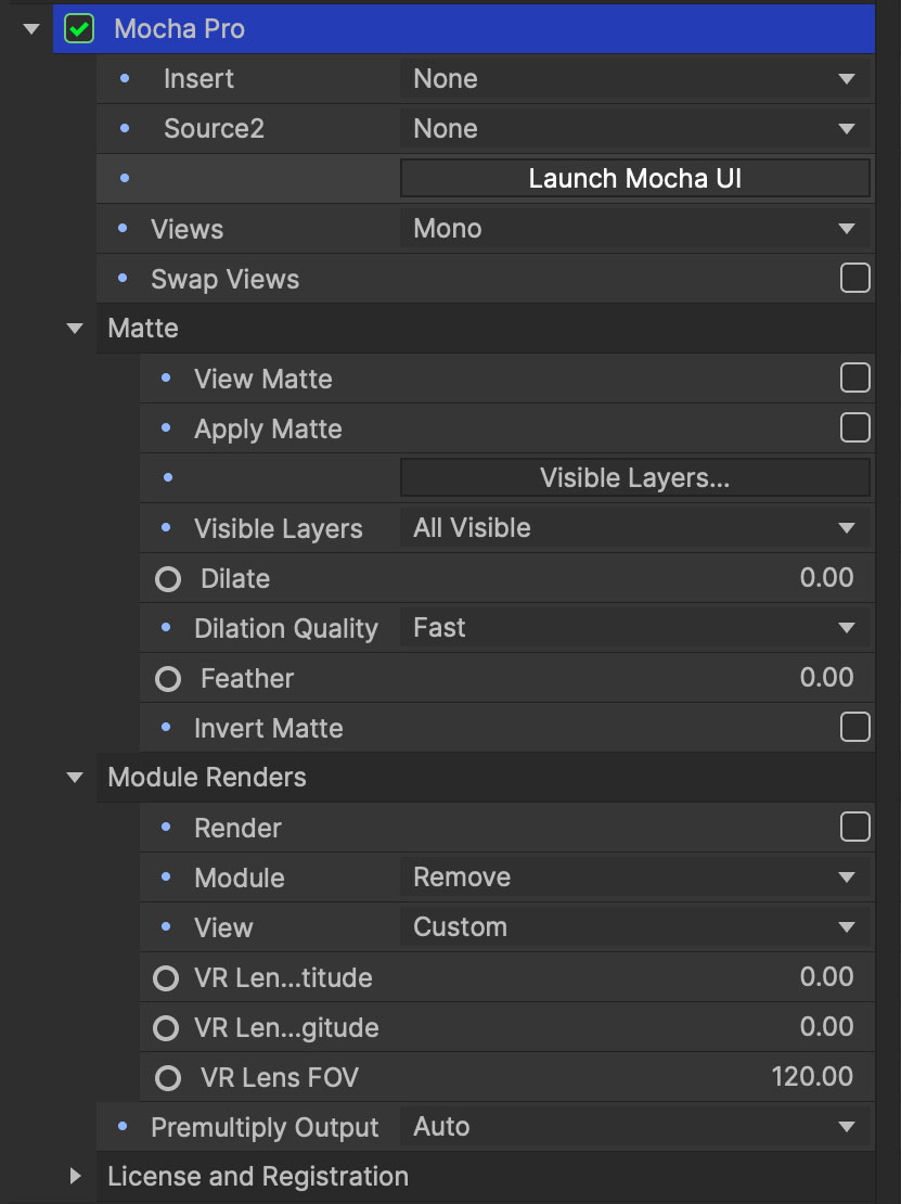
Controlling Mattes
Once you have tracked layers in Mocha, you can then control the mattes for these layers back in the plugin interface.

View Matte: Show the black and white matte from the Mocha layers chosen. This is very useful if you want to just see any problems with the matte, or you want to use the output as a track matte.
Apply Matte: Applies the chosen mattes to the current layer
Use Refined Mattes: On by default, this will render refined mattes if they are being used in the Matte module
Visible Layers: This button launches the Visible Layers dialog so you can select the layers you want visible as mattes. You can also edit the Layer names in this window.
Shape: This drop down lets you switch between All Visible and All mattes. All Visible mattes are controlled by the Visible Layers dialog.
Dilate: Dilates the edge of the matte in and out. A negative number brings the matte inward. A positive number expands it outward.
Dilate Quality: Options for Fast or High quality rendering of the matte dilation. We recommend High for final renders.
Feather: Applies a blur to the matte. This feathering is independent of the feathering of the individual layers inside Mocha.
Invert Mask: Inverts the currently visible mattes.
Create AE Mask: Creates native AE splines on the effect layer just like "Paste Mocha mask". This function is only available in After Effects.
Stereo output only
If you are using the 'Stereo' option in After Effects, you will need to select the "Stereo Output" view (Left or Right) that you want to apply output to.
If you are using Top/Bottom or Left/Right, the output will automatically double up to the split views.
Controlling Module Renders
Once you have set up layers in Mocha, you can then control the renders for each module back in the plugin interface.
Note that you do need to have set up and tracked the correct layers in order for a render to work back in the host.

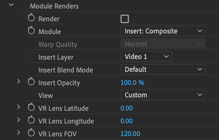
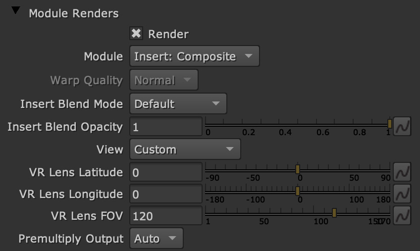
You have the following options to render a module back in the plugin:
Render: A simple checkbox to turn renders on and off.
Module: The module render you want to see. You have options of 'Insert: Composite', 'Insert: Cutout', 'Remove', 'Stabilize', 'Stabilize:Unwarp', 'Stabilize:Warp','Lens: Distort', 'Lens: Undistort' and 'Reorient'
Warp Quality: This drop down activates when you are using Stabilize:Unwarp and Stabilize:Warp options. It controls the render quality of the warp. See the Warp Mapping section of the stabilize module.
Insert Layer: For any inserts you want to apply to a layer surface and render back to the host.
Insert Blend Mode: Controls the Blending for Insert:Composite. If left to "Default" it will render what has been set inside the Mocha project. If changed, it will override all insert layers in the project.
Insert Opacity: Overrides the default insert opacity set inside the Mocha project.
There are also parameters for controlling the view in Lens:Distortion rendering for VR 360 footage.
See Using Mocha for 360 workflow for more on how to use the VR Lens controls.
Using Insert Layers from the host inside the plugin
To use the Insert Layer in Insert renders:
Pick the layer you want to use as an insert from the 'Insert Layer' drown down in the Mocha Pro effect
Launch the Mocha GUI
Create a layer (or pick an existing layer)
On the Layer Properties panel, choose the 'Insert Clip' dropdown
Select 'Insert Layer'
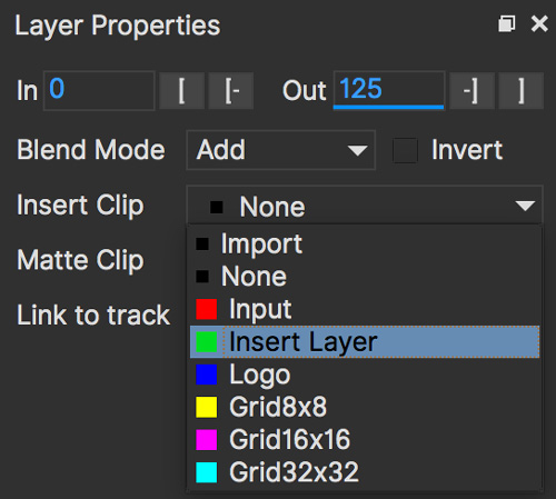
Your Insert should then appear inside the layer where you have placed your surface.
Controlling Tracking Data
If you have a tracked layer in Mocha you can see the output of its surface back in the After Effects interface.
Each point in the Tracking Data section is a point from the layer surface that automatically updates when you modify it inside Mocha.
To choose a layer to create tracking data from, click the 'Create Track Data' button in the Tracking Data section of the plugin.
![]()
Then choose ether the name or the cog of the layer you want to read tracking data from in the dialog that appears.
If you only have one layer in your Mocha project, Create Track Data will automatically create the data from the layer. There is no need to pick a layer. |
You can only choose one layer at a time.
![]()
Once you click 'OK', the plugin will generate keyframes to populate the tracking parameters in the plugin. You can then use this data to copy to other layers, or link via expressions.
This option is only available in the After Effects version of the plugin.
| Generating keyframe data can take some time for very long shots. You can cancel generation at any time when the progress bar appears. |
Applying Tracking Data Exports to Other layers
The plugin interface also allows you to apply tracking data to other layers without needing to export from the Mocha GUI.
Do do this, you generate the tracking data from a layer, as described above in Controlling Tracking Data.
You can then choose an export option at the bottom of the Tracking Data section:
Corner Pin: A standard corner pin effect
Corner Pin: (Support Motion Blur): A corner pin distortion with separate scale, rotation and position.
CC Power Pin: The CC Power Pin Effect
Transform: Scale, position and rotation
Clicking 'Apply Export' then copies the information to the specified layer.
Creating PowerMesh Nulls
The After Effects Mocha Pro Plug-In has a section for PowerMesh, which provides the ability to generate nulls based on each vertex in a tracked Mesh.
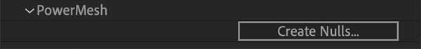
To create the nulls, you do the following:
Make sure you have tracked a Layer in Mocha Pro using the Mesh parameter
Select "Create Nulls…" under the PowerMesh section of the Adobe Mocha Pro Plugin interface
Choose the layer you want to generate nulls from
Click OK
If you are generating from a vertex-heavy mesh, Mocha will show a progress bar while generating the nulls.
Each Null will be created separately with its own keyframes.
Generating 3D Camera Data
The After Effects plugin interface can generate 3D Camera motion, nulls or lights from your Mocha Pro Camera Solves.
The create 3D Camera Data in AE:
Solve a Camera inside the Mocha Pro UI first using the Camera Solve module. If you have no camera data, nothing can be created in the AE interface.
Turn off any features you don’t want generated in the scene. This is important if you have a lot of features, as After Effects has an upper limit on how many layers it can generate.
Close the Mocha UI and save
In the Mocha Pro plugin interface, twirl down the '3D Camera Data' section
Choose the options you want to generate.
Click the
Create 3D Databutton
A progress bar will then appear and generate all the items you selected, along with the solved camera.
3D Camera Data options include:
Create Auto Features: Generate all features that were created by the auto solve. If this checkbox is off, Mocha will only generate solved features that were tracked specifically in Mocha
Features: Choose whether you want to generate all features or just the visible ones you set in the project. We recommend working with Visible features when you have a lot of points.
Feature Type: Choose whether you want to generate features as 3D Nulls or Lights. Lights are generally faster to generate and preview.
| You can also paste Mocha Camera data from the clipboard. For more on how to do this, see Exporting Camera Solves. |
Applying the Mocha Plugin for Adobe Premiere
The Mocha Pro Plugin for Adobe appears in the Effects menu like every other effect.
Simply apply the effect to the layer you want to work with.

The general workflow for the Mocha Adobe Plugin is as follows:
Select any additional source layers you want to use inside Mocha
Launch Mocha. This will load a full version of the Mocha interface that you can use just like the standalone version.
Use Mocha as required and then close and save. No rendering is required inside Mocha unless you want to.
Choose whether you want to use mattes, renders or any other data from Mocha back in the plugin interface.
| The Mocha Pro Plugin interface is almost exactly the same as the standalone interface, so most of the usual guide and video tutorials can be applied to the plugin. |
Using the Mocha GUI
Once you have applied the Mocha Pro effect, you can click on the Mocha button to launch the main interface.
This then becomes exactly like working in the standalone version of Mocha, with a few exceptions.
Firstly, you will notice you don’t need to set up a project like in the standalone version. The source layer is automatically loaded and ready to track in the view.
Secondly you don’t need to save out a project file (unless you want to export it). You just close and save the Mocha view when done and the project is saved inside the Effect like any other Adobe effect.
For further details on how to use anything inside the Mocha GUI, see the rest of the User Guide!
Controlling Mattes
Once you have tracked layers in Mocha, you can then control the mattes for these layers back in the plugin interface.

View Matte: Show the black and white matte from the Mocha layers chosen. This is very useful if you want to just see any problems with the matte, or you want to use the output as a track matte.
Apply Matte: Applies the chosen mattes to the current layer
Use Refined Mattes: On by default, this will render refined mattes if they are being used in the Matte module
Visible Layers: This button launches the Visible Layers dialog so you can select the layers you want visible as mattes. You can also edit the Layer names in this window.
Shape: This drop down lets you switch between All Visible and All mattes. All Visible mattes are controlled by the Visible Layers dialog.
Dilate: Dilates the edge of the matte in and out. A negative number brings the matte inward. A positive number expands it outward.
Dilate Quality: Options for Fast or High quality rendering of the matte dilation. We recommend High for final renders.
Feather: Applies a blur to the matte. This feathering is independent of the feathering of the individual layers inside Mocha.
Invert Mask: Inverts the currently visible mattes.
Controlling Module Renders
Once you have set up layers in Mocha, you can then control the renders for each module back in the plugin interface.
Note that you do need to have set up and tracked the correct layers in order for a render to work back in the host.
You have the following options to render a module back in the plugin:
Render: A simple checkbox to turn renders on and off.
Module: The module render you want to see. You have options of 'Insert: Composite', 'Insert: Cutout', 'Remove', 'Stabilize', 'Stabilize:Unwarp', 'Stabilize:Warp','Lens: Distort', 'Lens: Undistort' and 'Reorient'
Warp Quality: This drop down activates when you are using Stabilize:Unwarp and Stabilize:Warp options. It controls the render quality of the warp. See the Warp Mapping section of the stabilize module.
Insert Layer: For any inserts you want to apply to a layer surface and render back to the host.
Insert Blend Mode: Controls the Blending for Insert:Composite. If left to "Default" it will render what has been set inside the Mocha project. If changed, it will override all insert layers in the project.
Insert Opacity: Overrides the default insert opacity set inside the Mocha project.
There are also parameters for controlling the view in Lens:Distortion rendering for VR 360 footage.
See Using Mocha for 360 workflow for more on how to use the VR Lens controls.
Rendering Insert Layers
To use the Insert Layer in Insert renders:
Pick the video track you want to use as an insert from the 'Insert Layer' drown down in the Mocha Pro effect
Launch the Mocha GUI
Create a layer (or pick an existing layer)
On the Layer Properties panel, choose the 'Insert Clip' dropdown
Select 'Insert Layer'
Your Insert should then appear inside the layer where you have placed your surface.
Applying the Mocha Plugin for Avid Media Composer
| Due to extensive frame access by the Mocha plugin, it is recommended that you use Avid storage media (i.e. DNxHD) when working, rather than linked files. (Use of linked files which use codecs such as H.264 will significantly slow down render time as such media is not designed for random access.) |
The Mocha Pro Plugin for Adobe appears in the Effects menu like every other effect.
Simply apply the effect to the layer you want to work with.
The general workflow for the Mocha Adobe Plugin is as follows:
Select any additional source layers you want to use inside Mocha
Launch Mocha. This will load a full version of the Mocha interface that you can use just like the standalone version.
Use Mocha as required and then close and save. No rendering is required inside Mocha unless you want to.
Choose whether you want to use mattes, renders or any other data from Mocha back in the plugin interface.
| The Mocha Pro Plugin interface is almost exactly the same as the standalone interface, so most of the usual guide and video tutorials can be applied to the plugin. |
Using the Mocha GUI
Once you have applied the Mocha Pro effect, you can click on the Mocha button to launch the main interface.

This then becomes exactly like working in the standalone version of Mocha, with a few exceptions.
Firstly, you will notice you don’t need to set up a project like in the standalone version. The source layer is automatically loaded and ready to track in the view.
Secondly you don’t need to save out a project file (unless you want to export it). You just close and save the Mocha view when done and the project is saved inside the Effect like any other AVX effect.
For further details on how to use anything inside the Mocha GUI, see the rest of the User Guide!
Controlling Mattes
Once you have tracked layers in Mocha, you can then control the mattes for these layers back in the plugin interface.

View Matte: Show the black and white matte from the Mocha layers chosen. This is very useful if you want to just see any problems with the matte, or you want to use the output as a track matte.
Apply Matte: Applies the chosen mattes to the current layer
Use Refined Mattes: On by default, this will render refined mattes if they are being used in the Matte module
Visible Layers: This button launches the Visible Layers dialog so you can select the layers you want visible as mattes. You can also edit the Layer names in this window.
Visible Layers Dropdown: This drop down lets you switch between All Visible and All mattes. All Visible mattes are controlled by the Visible Layers dialog.
Dilate: Dilates the edge of the matte in and out. A negative number brings the matte inward. A positive number expands it outward.
Dilate Quality: Options for Fast or High quality rendering of the matte dilation. We recommend High for final renders.
Feather: Applies a blur to the matte. This feathering is independent of the feathering of the individual layers inside Mocha.
Invert Matte: Inverts the currently visible mattes.
Controlling Module Renders
Once you have set up layers in Mocha, you can then control the renders for each module back in the plugin interface.
Note that you do need to have set up and tracked the correct layers in order for a render to work back in the host.

You have the following options to render a module back in the plugin:
Render: A simple checkbox to turn renders on and off.
Module: The module render you want to see. You have options of 'Insert: Composite', 'Insert: Cutout', 'Remove', 'Stabilize', 'Stabilize:Unwarp', 'Stabilize:Warp','Lens: Distort', 'Lens: Undistort' and 'Reorient'
Warp Quality: This drop down activates when you are using Stabilize:Unwarp and Stabilize:Warp options. It controls the render quality of the warp. See the Warp Mapping section of the stabilize module.
Insert Layer: For any inserts you want to apply to a layer surface and render back to the host. Choose from the current layer or below the current video track.
Insert Blend Mode: Controls the Blending for Insert:Composite. If left to "Default" it will render what has been set inside the Mocha project. If changed, it will override all insert layers in the project.
Insert Opacity: Overrides the default insert opacity set inside the Mocha project.
There are also parameters for controlling the view in Lens:Distortion rendering for VR 360 footage.
See Using Mocha for 360 workflow for more on how to use the VR Lens controls.
| Processing larger frame sizes and more complex rendering in Mocha may take a long time per frame. When a frame render exceeds a certain interval in Media Composer, a BlipPlayer error can occur. If you see this message, you should render the effect prior to playing back, or preview the render inside the Mocha UI before rendering back on the timeline. |
Rendering Insert Layers
To use the Insert Layer in Insert renders:
Pick the video track you want to use as an insert from the 'Insert Layer' drown down in the Mocha Pro effect. This will most commonly be "1st Below" the current layer with the effect applied.
Launch the Mocha GUI
Create a layer (or pick an existing layer)
On the Layer Properties panel, choose the 'Insert Clip' dropdown
Select 'Insert Layer'
Your Insert should then appear inside the layer where you have placed your surface.
Stereo Workflow
To work on a stereo shot in Media Composer:
Import a Top/Bottom or Left/Right combined stereo file
Choose the stereo type from the 'Views' drop down
Open Mocha, and the views will be mapped automatically to the left and right views.
| Avid’s native stereo support is not supported by Mocha at present, so you can only use Top/Bottom or Left/Right combined stereo files. |
Applying the Mocha OFX Plugin
| The OFX version of the Mocha Plugin is fully supported in Nuke, Fusion, HitFilm Pro, Vegas Pro and Silhouette. |
If you have a license for the OFX version it will work in any of the OFX hosts listed below.
Keep in mind that while the Mocha OFX plugin is designed to be used in multiple applications, it does not support all OFX hosts.
In many cases some functionality may be possible for unsupported hosts, but there is no guarantee of functionality or stability, so please take care when experimenting!
Adding the Mocha Plugin inside Autodesk Flame
Inside Flame, the Mocha Pro Plugin for OFX appears in the OpenFX Plugin loader panel like every other OFX plugin.
To get full use of the Mocha Pro plugin, we recommend using it as a batch effect.
Click on the FX button and then click
Create Batch FX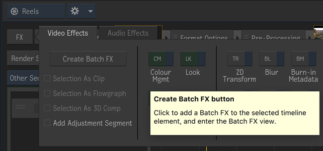
Drag a new OpenFX plugin into the Batch FX graph

In the OpenFX plugin panel, click 'Load Plugin' and navigate to 'Boris FX Mocha' and choose 'Mocha Pro'

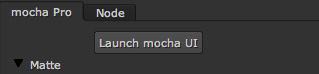
Once loaded into the Effects panel, you can just click the 'Launch Mocha UI' button to open the Mocha Pro interface.

Adding the Mocha Plugin inside Blackmagic Design Fusion Studio
Inside Fusion Studio, the Mocha Pro Plugin for OFX appears in the Tool menu like every other effect.
Just choose 'Boris FX Mocha' > 'Mocha Pro'.
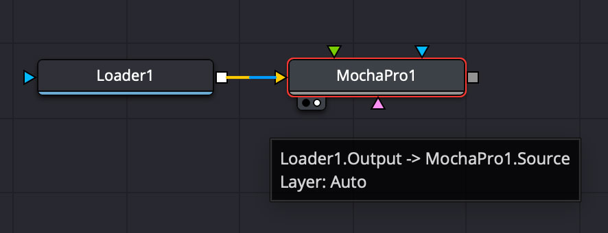
Once loaded into the flow graph, simply plug the image node you want to work with into the 'Source' input of the Mocha Pro effect node.
Adding the Mocha Plugin inside The Foundry Nuke
Inside Nuke, the Mocha Pro Plugin for OFX appears in the toolbar menu like every other effect.
You can also call the Mocha Pro effect from the Tab key by searching for 'Mocha Pro' or right-click and choose 'Boris FX Mocha' > 'Mocha Pro'.

Once loaded into the node graph, simply plug the image node you want to work with into the 'Source' input of the Mocha Pro effect node.
| Nuke has native OFX stereo support and so only requires one Source input if you are using the "Stereo" option. If you have separate left and right eye sources, apply a "Join Views" node to combined them and feed the output into the Source input of the Mocha node. |
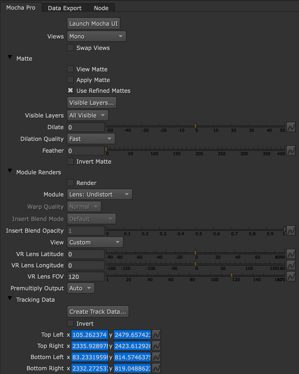
Tracking Data Generation
The Mocha Pro OFX plugin can generate tracking data from a layer’s surface directly in the plugin interface.
This data can either be linked to other nodes via expressions, or be used in conjunction with the Data Export tab.
To generate data:
Track your project as normal inside the Mocha UI
Close and save the Mocha project
Twirl down the
Tracking Datasection of the OFX plugin interface.Click the
Create Track Data…buttonIf you have more than one layer in the Mocha project, a layer chooser dialog will appear to select the layer you want to create the data from. Otherwise it will generate automatically.
This then populates the 4 sets of fields with keyframes. Each x/y field corresponds to the corner position of the surface of the selected Mocha layer.
The Data Export Tab
The Nuke OFX plugin has addtional export options to create tracking nodes directly in the node graph.

To create a tracked node:
Track your project as normal inside the Mocha UI
Close and save the Mocha project
Click the
Data Exporttab in the Mocha Pro plugin interfaceSelect a data node type:
Tracker node
CornerPin2D node
Select the type of keyframing you want:
Linked: This links the data to the Mocha Pro project data. If you update the surface in Mocha Pro, the linked data will also update when you regenerate the data.
Baked: This bakes the keyframes so the node can operate independently of Mocha.
If you have more than one layer in the Mocha project, a layer chooser dialog will appear to selec the layer you want to create the data from. Otherwise it will generate automatically.
You can of course still export directly via the Mocha Pro interface if you prefer. See Exporting Tracks to Nuke.
Adding the Mocha Plugin inside Silhouette
In Silhouette, Mocha Pro Plugin for OFX appears in the nodes menu like every other effect.
Mocha Pro node in Silhouette:

Once loaded into the tree window, simply plug the image node you want to work with into the 'Source' input of the Mocha Pro effect node.
Linear Workflow
Silhouette includes Linear support for the Mocha plugin.
If you are using rec709 8-bit images, you need to enable the 'Mocha > Linearize Images In Mocha Pro' preference in Silhouette so images look correct in the Mocha GUI.
When using EXR or Cineon images, this preference should remain off.
You can also use the built-in OCIO preferences in the Mocha Viewer Preferences.
Adding the Mocha Plugin inside Vegas Pro
Inside Vegas Pro, the Mocha OFX Plugin appears under 'Boris FX Mocha' in the Plug-in Chooser dialog for the following effect chains:
Event FX: Click the effect icon on the video event segment you want and then select the Mocha effect and click OK.
Track FX: Click the effect icon on the appropriate video track and then select the Mocha effect and click OK.
Track Composite Mode: Choose 'Custom…' in the Compositing Mode options then select the Mocha effect and click OK.
Mocha Pro node in Vegas Plug-in Chooser:
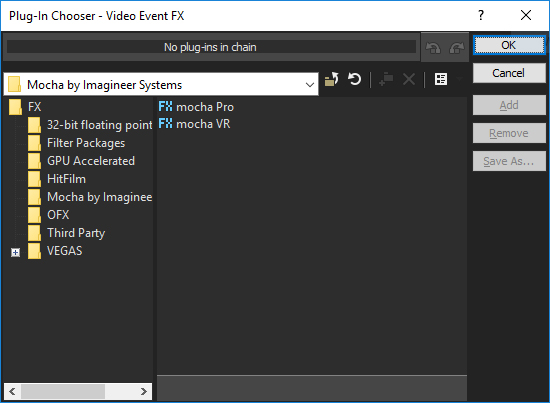
Once loaded, you can begin with the 'Launch Mocha UI' button at the top of the effect panel.

Using the Insert Layer clip in Vegas
Mocha uses two sources from the timeline for inserting clips: The main background image source to track from and a secondary image source to insert into a tracked layer.
To use a secondary source input in Vegas for Insert clips you need to composite your tracks together:
Set the Insert clip you want to use as the parent layer and the plate you want the insert to be rendered over as the child
Click the Track Compositing mode on the parent insert layer and select 'Custom…'

Select the Mocha effect and click OK
Launch the Mocha GUI in the Composite Mode panel
This will then load the secondary source into any layer Insert clip dropdown as a clip called 'Insert Layer'. See Rendering Insert Layers below.
| Vegas Pro has native stereo support. When working with stereo in Mocha you will only see two options: Mono and Stereo. The "Stereo" option will read the native set up and feed in both eyes to the Mocha GUI. |
Creating Vegas Bezier Masks
| This feature is only available in Vegas Pro 21 and above. |
If you don’t want to use the matte rendering to apply mattes from Mocha, you can click the Create Masks… button to generate a Bezier masking effect in Vegas.
This will take the spline layers inside the Mocha project and convert them to native bezier masks.
The masks generated are determined by either what layers you have visible in the Mocha project,
or you can select to export all of them by choosing "All" from the Visible Layers dropdown.
Vegas Bezier Masking limitations Currently, the Bezier Mask effect in Vegas has a limit of 5 Masks per effect. This means that if you have more than 5 splines or contours in your Mocha project |
Controlling Tracking Data
| This feature is only available in Vegas Pro 21 and above. |
If you have a tracked layer in Mocha you can see the output of its surface back in the Vegas interface.
Each point in the Tracking Data section is a point from the layer surface that automatically updates when you modify it inside Mocha.
To choose a layer to create tracking data from, click the 'Create Track Data' button in the Tracking Data section of the plugin.
![]()
Then choose the layer you want to read tracking data from in the dialog that appears. You can only choose one layer at a time.
![]()
Once you click OK, the plugin will generate keyframes to populate the tracking parameters in the plugin. You can then use this data to generate tracked PiP effects on other clips.
| Generating keyframe data can take some time for very long shots. You can cancel generation at any time when the progress bar appears. |
Applying Tracking Data Exports to Other layers
The plugin interface also allows you to apply tracking data to other layers without needing to export from the Mocha GUI.
If you are planning to insert media on top of your tracked source footage, it’s recommended the insert media is placed above the source clip in the timeline.
To apply Mocha tracking data to another clip in the Vegas timeline:
Generate the tracking data from a layer, as described above in Controlling Tracking Data
Click 'Apply Export…'. This will open the native Motion Tracking dialog in Vegas
Select the bottom right arrow in the Motion Tracking dialog. This will show your available clips to apply the tracking data to.
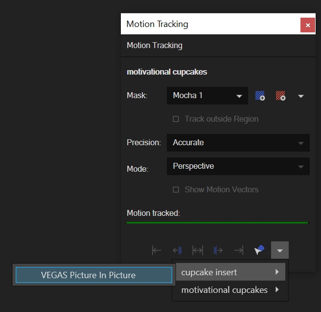
Select the clip from the dropdown that you want to apply the tracking data to, and select "Vegas Picture in Picture"
An alternative approach is to use the Motion Track Transfer cursor:
Generate the tracking data from a layer, as described above in Controlling Tracking Data
Click 'Apply Export…'. This will open the native Motion Tracking dialog in Vegas
Select and hold the
Motion Track Transferbutton in the Motion Tracking dialog. This will change your cursor to a pick tool.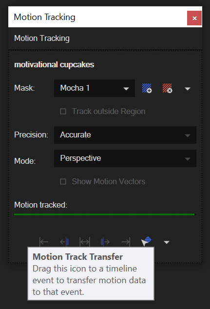
Still holding down the left mouse button, drag the cursor to the clip on your timeline that you want to apply the tracking data to, and select "Vegas Picture in Picture"
Both these approaches will generate a new Picture in Picture (PiP) effect on the target clip.
Fixing Media that Doesn’t Fit to the Tracking Data Correctly

If your inserted clip media looks squeezed or out of shape, this is most likely because of the default settings in the Event FX Pan/Crop tool.
To fix this, click on Pan/Crop tab to the left of Picture in Picture.

You need to change the following settings in Pan/Crop:
Maintain aspect ratio: Set to "No"
Stretch to fill frame: Set to "No"
You should then see the screen image fit correctly.
Basic workflow for the Mocha OFX Plugin
One your source clip is hooked up to you Mocha Pro Effect, the general workflow for the Mocha OFX Plugin is as follows:
Select any additional source you want to use as an insert in Mocha and plug it into the 'Insert' input (See Rendering Insert Layers below.)
Launch the Mocha UI using the button at the top of the panel. This will load a full version of the Mocha interface that you can use just like the standalone version.
Use Mocha as required and then close and save. No rendering is required inside Mocha unless you want to.
Choose whether you want to use mattes, renders or any other exported data from Mocha back in the plugin interface.
| The Mocha Pro Plugin interface is almost exactly the same as the standalone interface, so most of the usual guide and video tutorials can be applied to the plugin. Plugin interface examples below use the Nuke UI. |
Using the Mocha GUI
Once you have applied the Mocha Pro effect, you can click on the 'Launch Mocha UI' button to launch the main interface.
This then becomes exactly like working in the standalone version of Mocha, with a few exceptions.
Firstly, you will notice you don’t need to set up a project like in the standalone version. The source layer is automatically loaded and ready to track in the view.
Secondly you don’t need to save out a project file (unless you want to export it). You just close and save the Mocha view when done and the project is saved inside the effect.
For further details on how to use anything inside the Mocha GUI, see the rest of the User Guide!
Controlling Mattes
Once you have tracked layers in Mocha, you can then control the mattes for these layers back in the plugin interface.

View Matte: Show the black and white matte from the Mocha layers chosen. This is very useful if you want to just see any problems with the matte, or you want to use the output as a track matte.
Apply Matte: Applies the chosen mattes to the source node.
Use Refined Mattes: On by default, this will render refined mattes if they are being used in the Matte module
Visible Layers Button: This button launches the Visible Layers dialog so you can select the layers you want visible as mattes. You can also edit the Layer names in this window.
Visible layers Dropdown: This drop down lets you switch between All Visible and All mattes. All Visible mattes are controlled by the Visible Layers dialog.
Dilate: Dilates the edge of the matte in and out. A negative number brings the matte inward. A positive number expands it outward.
Dilate Quality: Options for Fast or High quality rendering of the matte dilation. We recommend High for final renders.
Feather: Applies a blur to the matte. This feathering is independent of the feathering of the individual layers inside Mocha.
Invert Matte: Inverts the currently visible mattes.
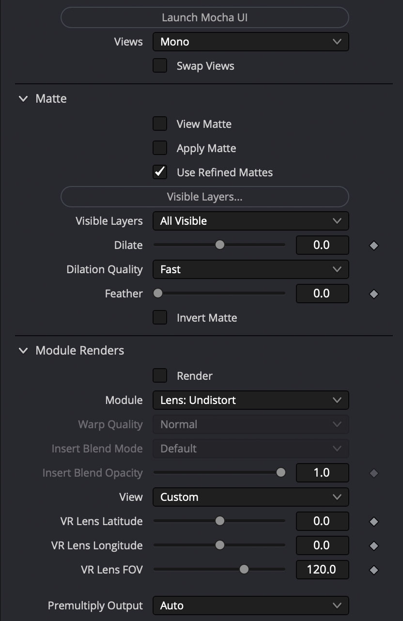
Controlling Module Renders
Once you have set up layers in Mocha, you can then control the renders for each module back in the plugin interface.
Note that you do need to have set up and tracked the correct layers in order for a render to work back in the host.
You have the following options to render a module back in the plugin:
Render: A simple checkbox to turn renders on and off.
Module: The module render you want to see. You have options of 'Insert: Composite', 'Insert: Cutout', 'Remove', 'Stabilize', 'Stabilize:Unwarp', 'Stabilize:Warp','Lens: Distort', 'Lens: Undistort' and 'Reorient'
Warp Quality: This drop down activates when you are using Stabilize:Unwarp and Stabilize:Warp options. It controls the render quality of the warp. See the Warp Mapping section of the stabilize module.
There are also parameters for controlling the view in Lens:Distortion rendering for VR 360 footage.
See Using Mocha for 360 workflow for more on how to use the VR Lens controls.
Rendering Insert Layers
You can use secondary clips in the host application to render tracked inserts into your shots.
See the User Guide Chapter on the Insert Module for more details on manipulating and warping inserts.
To use the Insert input from your host application in Insert renders:
Pick the image you want as an insert and make it available for the Mocha plugin to use:
For node based compositors you can plug the insert image into the 'Insert' input on the the Mocha Pro effect node.
In Vegas you need to make the insert image the parent in compositing mode. See Using the Insert Layer clip in Vegas for this method.
In HitFilm, you select the insert image from one of your other layers in the comp listed in the "Insert" dropdown
Launch the Mocha GUI
Create a layer (or pick an existing layer)
On the Layer Properties panel, choose the 'Insert Clip' dropdown
Select 'Insert Layer'
Your Insert should then appear inside the layer where you have placed your surface.
Alternatively you can import an image or sequence directly to the plugin:
Launch the Mocha GUI
Create a layer (or pick an existing layer)
On the Layer Properties panel, choose the 'Insert Clip' dropdown
Select 'Import'
Import an image or image sequence
The imported Insert should then appear inside the layer where you have placed your surface.
Once you have set up your render in the Insert Module, you can then render back to the host:
Close and save the Mocha Project
Open the "Module renders" section of the plugin effect interface
Select either "Insert: Composite" or "Insert: Cutout" from the "Module" dropdown
Click "Render" checkbox to render the insert
You can also adjust the Insert Blend Mode and the Insert Opacity from the plugin interface without needing to go back into Mocha:
Insert Blend Mode: Controls the Blending for Insert:Composite. If left to "Default" it will render what has been set inside the Mocha project. If changed, it will override all insert layers in the project.
Insert Opacity: Overrides the default insert opacity set inside the Mocha project.
Dealing with Alpha Channel Input and Output
In cases where your input source has an alpha channel, you may wish to change the Alpha view inside the Mocha GUI.
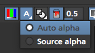
You can either turn Alpha off entirely by toggling off the button, or choose from one of the following options:
Auto alpha: Reads in alpha if it is not opaque or premultiplied. This is the default setting.
Source alpha: This option shows the alpha as given from the source.
Auto alpha may be necessary when working with some source inputs in Nuke.
When rendering back out to the host, there are cases where you may also need to premultiply the alpha using the premultiply options in the plugin interface.
In these cases you can choose an option from the 'Premultiply' dropdown:
Auto: Premultiplies based on the original source input
On: Always premultiply output
Off: Never premultiply output
You can also choose to premultiply using standard premultiply nodes.
Stereo Workflow
To work on a stereo shot in your OFX host:
Import separate stereo views, a Top/Bottom or Left/Right combined stereo file
Choose the stereo type from the 'Views' drop down: 'Top/Bottom', 'Left/Right' or 'Stereo'
If you are using the 'Stereo' option, make sure you are applying the effect to the Left eye footage and choose your right-eye source input
Open Mocha, and the views will be mapped automatically to the left and right views.
| Some OFX hosts handle stereo support differently. See your specific host notes in this chapter for instructions. Especially Nuke and Vegas. |
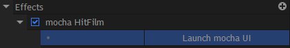
Applying the Mocha HitFilm or Mocha Pro Plugin inside HitFilm
We now include a light version of Mocha, called Mocha Hitfilm, as a plugin in HitFilm Pro 2017 onwards. This includes:
Tracking and roto export for HitFilm
3D Camera solving
Matte rendering
However, you can also use the Mocha Pro OFX plugins in the HitFilm interface.
Adding the Mocha Plugin to a layer
To add Mocha, simply locate it in the Effects panel like any other effect and drag it onto your layer.
Mocha HitFilm Effect Controls in a HitFilm comp:
Basic workflow for the Mocha Plugin in HitFilm
Once your layer is hooked up to your Mocha Effect, the general workflow for the Mocha Plugin is as follows:
Launch the Mocha UI using the 'Launch Mocha UI' button at the top of the panel. This will load a full version of the Mocha interface that you can use just like the standalone version.
Use Mocha as required
Export any data if needed (tracks, shapes or camera solve data) then close and save
Choose any mattes you want to use from Mocha back in the plugin interface
If you are using Mocha Pro, choose the renders you wish to use from the "Module Renders" section and check "Render"
| The Mocha HitFilm Plugin interface is almost exactly the same as the standalone interface, so most of the usual guide and video tutorials can be applied to the plugin. |
Using the Mocha GUI
Once you have applied the Mocha effect, you can click on the 'Launch Mocha UI' button to launch the main interface.
This then becomes exactly like working in the standalone version of Mocha, with a few exceptions.
First, you will notice you don’t need to set up a project like in the standalone version. The source layer is automatically loaded and ready to track in the view.
Secondly, you don’t need to save out a project file (unless you want to export it). You just close and save the Mocha view when done and the project is saved inside the effect.
For further details on how to use anything inside the Mocha GUI, see the rest of the User Guide!
Controlling Mattes
Once you have tracked layers in Mocha, you can then control the mattes for these layers back in the plugin interface.

View Matte: Show the black and white matte from the Mocha layers chosen. This is very useful if you want to just see any problems with the matte, or you want to use the output as a track matte.
Apply Matte: Applies the chosen mattes to the source node.
Use Refined Mattes: On by default, this will render refined mattes if they are being used in the Matte module
Visible Layers Button: This button launches the Visible Layers dialog so you can select the layers you want visible as mattes. You can also edit the Layer names in this window.
Visible layers Dropdown: This drop down lets you switch between All Visible and All mattes. All Visible mattes are controlled by the Visible Layers dialog.
Dilate: Dilates the edge of the matte in and out. A negative number brings the matte inward. A positive number expands it outward.
Dilate Quality: Options for Fast or High quality rendering of the matte dilation. We recommend High for final renders.
Feather: Applies a blur to the matte. This feathering is independent of the feathering of the individual layers inside Mocha.
Invert Matte: Inverts the currently visible mattes.
Controlling Mocha renders in HitFilm
If you are using the Mocha Pro version of the plugin, controlling renders is exactly like the standard OFX rendering controls.
See Controlling Renders and Rendering Insert Layers in the section above.
360 VR and Stereo Views Workflow
The Mocha Pro plugin supports different types of 360 and Stereo footage via the "Views" drop down:
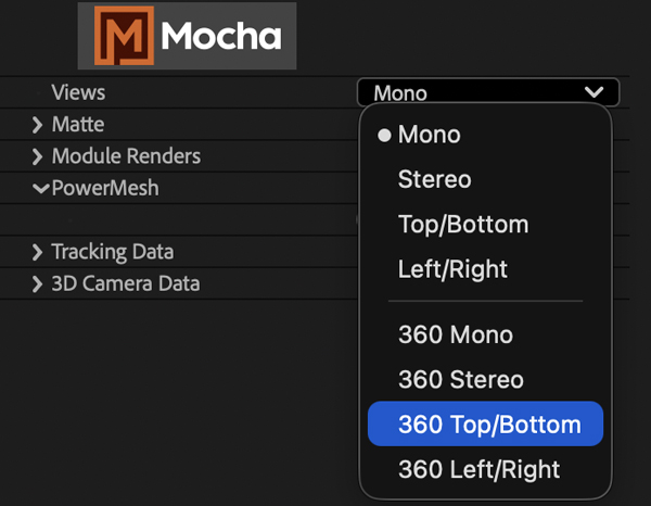
The first 4 Views options are for non-360 footage:
Mono: This is the default option and works with standard (non-stereo) footage.
Stereo (Separate eyes): This takes two separate footage streams. When chosen, the option to choose another source for the right eye is enabled. If you are using the 'Stereo' option, you will need to select the "Stereo Output" view (Left or Right) that you want to apply output to.
Top/Bottom: Top/Bottom is also commonly known as "Over/Under". When used, Mocha will split the footage exactly in half horizontally and use the Top and Bottom halves for each eye. The output to the host will automatically double up to the split views.
Left/Right: Left/Right is also commonly known as "Side by Side". When used, Mocha will split the footage exactly in half vertically and use the Left and Right halves for each eye. The output to the host will automatically double up to the split views.
Choosing one of the 360 options automatically sets your Mocha project to be Equirectangular 360. This will enable VR features:
360 Mono: Sets the project to non-stereo 360 footage.
360 Stereo: This takes two separate 360 footage streams. When chosen, the option to choose another source for the right eye is enabled. If you are using the 'Stereo' option, you will need to select the "Stereo Output" view (Left or Right) that you want to apply output to.
360 Top/Bottom: Top/Bottom is also commonly known as "Over/Under". When used, Mocha will split the footage exactly in half horizontally and use the Top and Bottom halves for each eye. The output to the host will automatically double up to the split views.
360 Left/Right: Left/Right is also commonly known as "Side by Side". When used, Mocha will split the footage exactly in half vertically and use the Left and Right halves for each eye. The output to the host will automatically double up to the split views.
You can also choose to Swap the Left and Right eye input by checking the Swap Views checkbox.
Some hosts will require different handling for Stereo sources:
Nuke: Nuke has native OFX stereo support and so only requires one Source input if you are using the "Stereo" option. If you have separate left and right eye sources, apply a "Join Views" node to combined them and feed the output into the Source input of the Mocha node.
Vegas Pro: Vegas Pro also has native stereo support. You will only see two options: Mono and Stereo. The "Stereo" option will read the native set up and feed in both eyes to the Mocha GUI.
Media Composer: Avid’s native stereo support is not supported by Mocha at present, so you can only use Top/Bottom or Left/Right combined stereo files.
In addition to the controls listed above, VR features also contain a separate area in the Module Renders section to control lens distortions without having to first open the Mocha Pro GUI:

As you go through the user guide, you will see sections on how to apply Mocha techniques to your stereo footage where relevant.
Loading Projects containing the Mocha VR Plugin
When you load a project that contains the old Mocha VR plugin, you will notice that Mocha VR is labelled as "Legacy".
This is because all Mocha VR features have been rolled into Mocha Pro and a Mocha VR plugin stub is kept to avoid breaking compatibility with your old projects.
When you want to start a new VR project, we highly recommend using the Mocha Pro plugin rather than the legacy Mocha VR plugin, as this compatibility feature may be removed in future versions.
See (360 VR and Stereo Views Workflow ) above for how to set the 360 VR modes in new Mocha Pro projects.
Starting a New Project
Workflow inside Mocha
Mocha workflow is designed around a project structure. It is good practice to only work on one shot per project file to minimize layer management and to keep the work streamlined.
Import your footage
Draw a loose spline around the shape you want to track
Track the spline
Set the 'Surface', or corner pin where you want the inserted image
Adjust your track if necessary
Export the completed track
Import your footage
Draw a loose spline around the shape you want to track.
Track the spline
Adjust your track if necessary
Add new shapes for rotoscoping and link them to your track
Adjust shapes where necessary
Export the rendered mattes or the shape data
Creating a New Project in the Mocha Standalone application
When you start the application you are presented with an empty workspace. No footage is loaded and most of the controls are consequently disabled.
To begin working, you must open an existing project or start a new project.

Select the clip to import by clicking on the Choose… button to the right of the top line. This will bring up a file browser, where you can select almost any industry standard file formats. Image sequences will show up as individual frames. You can select any one of the frames and the application will automatically sequence the frames as a clip when importing.
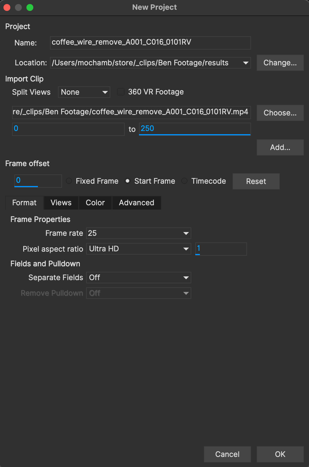
Name
A project name will automatically be generated based on the filename of the imported footage, but you can change it by editing the Name field.
Location
Your project file and cache files will output to a directory called "Results" by default. This is created in the same folder your clip is imported from. You can change this using the Change… button or using the dropdown box to set a different relative or absolute path.
Frame Range
The range of frames to import. We recommend to only work with the frames you need, rather than importing very large clips or multiple shots edited together.
Frame offset
This is set to the starting frame number or timecode by default. You can also define a fixed frame (You can set a default for the fixed frame in Preferences).
You also have the option to view as Timecode or Frame numbers. If your clip has an embedded timecode offset and you switch to Timecode, the offset will be used in your project.
If you need to adjust this value later, you can open Project Settings from the file menu. See "Project Frame Offsets and Clip Frame Offsets" below for more details.
Frame Rate
Normally this is automatically detected, but you have options to adjust if necessary. You can choose from the dropdown, or click inside the dropdown to set your own frame rate.
Make sure you check the frame rate before you close the New Project dialog.
If you need to adjust this value later, you can open Project Settings from the file menu.
Separate Fields
If you are using interlaced footage, set your field separation here to Upper or Lower. Make sure you check your fields match your footage before you close the New Project dialog. If you don’t set them correctly, you cannot modify them and will have to restart the project.
Remove Pulldown
If your footage has pulldown, set it here.
Advanced options
Caching
If you wish the clip to be cached into memory, check the Cache clip checkbox here. Caching is recommended if you are working a computer that has fast local storage, but your shot is stored in a slow network location. If your shot is already stored on fast storage, you don’t need to cache. More often than not, you can leave this setting off.
Color Options
The color options help you set up the default OCIO config for the project.
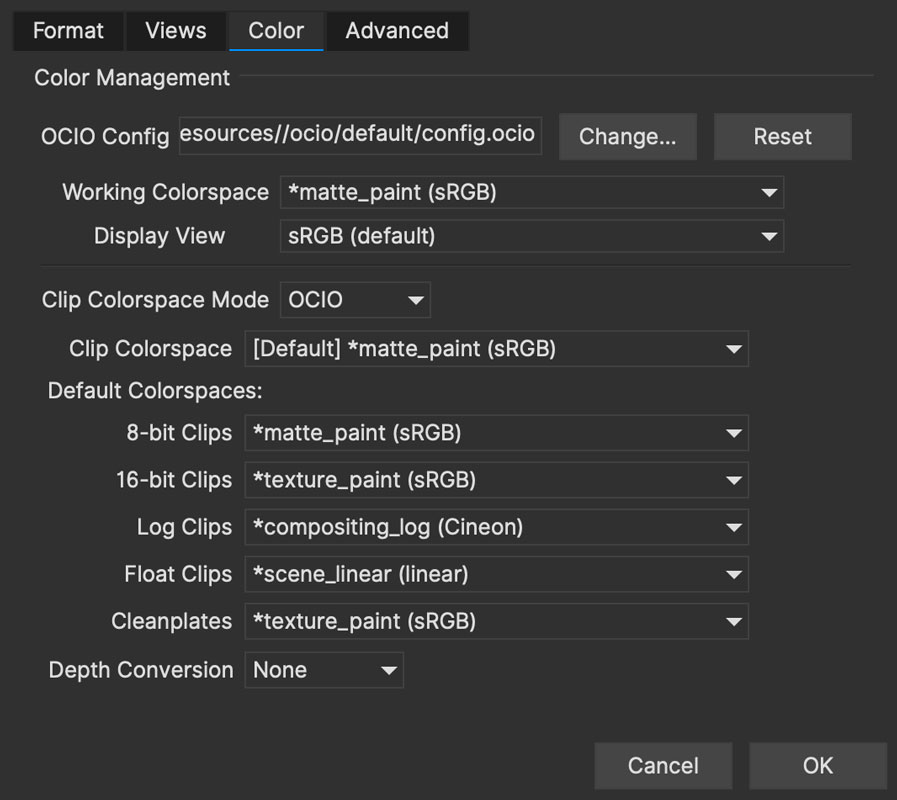
Here the Color Space section is divided into several sections:
OCIO config: Here you can change the OCIO config or reset back to the default.
Working Color Space: The color space or Role you want to work with
Display View: The color view you want to display, such as sRGB, Rec709 etc
Clip Color space Mode: This is either OCIO or Legacy, which is important if you are opening projects from an earlier version of Mocha.
Default Color Spaces: Here you can define what color space to set for clips at various bit depths.
Depth conversion: This lets you define if you want to convert clips by default to 8-bit or Float.
See OpenColorIO (OCIO) Color Management for more details on color management.
Setting Up a New Project For VR 360
Mocha Pro supports Equirectangular 360 Footage. To set the project to be in 360 mode, check the '360 VR Footage' checkbox after you import your clip.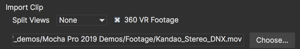
Setting Up a New Project For Stereo
When you start a New Project you are also presented with the option of creating a multiview project in the Views tab.

If you check Multiview project you are then presented with the view names and their abbreviated names.
The abbreviated name is used in the interface for the view buttons, but is also used as the suffix for renders.
You can also choose the hero view. By default this is the left. Defining a hero eye determines the tracking and roto order for working in the views.
If you are using Top/Bottom or Left/Right footage combined in a single frame, select an option from the Split Views drop down:
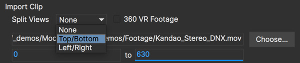
If you want to define separate streams of footage for the stereo views, you can add additional footage streams view the Add button below the initial clip chooser.

If you forget to set up Multiview when you start a new project, you can set it in the new Project Settings Dialog from the File menu.
Once you are in Multiview mode, you will see a colored border around the viewer based on the current view you are in.
This is to help artists to identify which view they are currently in without having to refer to the buttons
You can switch between Views by pressing the corresponding L|R buttons in the view controls, or using the default 1 and 2 keys on the keyboard.
You can swap views or change the Split View mapping from the View Mapping subtab under the Clip module:

Creating a New Project in the Mocha Pro Plugin
The Mocha Pro plugin has a slightly different project workflow to the stand alone Mocha applications.
Apply the Mocha Pro effect to your layer or footage track
Launch Mocha from effects panel in your host application
This action loads the footage from the host clip you applied the effect to. It automatically applies the correct frame rate and other clip settings, so there is no need for the standard new project dialog.
After you have done the usual work inside the Mocha Pro interface, you simply close and save the Mocha Pro GUI and then you can control the output from the effect editor interface.
For general guide to workflow with the Mocha plugin, see Using the Mocha Pro Plugin.
For setting up a new stereo project with the plugin, see Plugin Stereo Workflow.
Creating a New Project in the BCC 10 Mocha PixelChooser
Boris FX introduced the Mocha PixelChooser in BCC 10. The plugin has a slightly different project workflow to the stand alone Mocha applications.
Apply a BCC effect to your layer or footage track
Launch Mocha from the PixelChooser section of the plugin. You may be able to launch Mocha to apply a
Mocha Mask…or track withMocha Param Track…depending on the effect type.
![]()
This action loads the footage from the host clip you applied the effect to. It automatically applies the correct frame rate and other clip settings, so there is no need for the standard new project dialog.
After you have done your tracking and/or roto work, you simply close and save the Mocha PixelChooser and it applies any visible layers as mattes back to the effect.
| The Mocha PixelChooser plugin is limited to Tracking and Roto and only exports data formats to BCC plugins. |
Setting the In and Out Points
If you will only be working on a section of the shot you can use the In and Out points to set the range on the timeline. Note that the In and Out points affect the range of the Überkey button. You can zoom the timeline to only show you the part between you In and Out points by clicking the Zoom Timeline button.
Project Frame Offsets and Clip Frame Offsets
Frame offsets are important to get right in Mocha so that they export correctly to your target program.
There are two kinds of frame offsets:
Project Frame Offset: This frame offset sets the starting frame for keys in your timeline. For example if you have imported a sequence of 100 frames and you need the index of frames to start at 1001, you can change this under the Project Settings in the file menu.
Clip Frame Offset: This frame offset is to offset the actual clip frames to slide the starting point of the clip back and forth. You can adjust clip frame offset under the Display tab in the Clip module.
For the vast majority of cases the Project Frame Offset is the value you want to adjust for working with data.
The frame offset is usually already set correctly at the New Project dialog stage, but there may be cases where offsets change, such as adding new clip frames.
Tips for New Projects
Only import as much as you need
Working with very long files can be time consuming for the artist and can slow down the tracking as it searches for more frames. Try to only use what you need, and work on individual shots, rather than multiple shots in one piece of footage.
Frame rate, dimensions and pixel aspect ratio are important
Make sure these values match the settings in your compositor or editor, otherwise tracking and shape data will not match when you export it.
If you are unsure which field your interlaced footage is in, import it and check
If you quickly start your project with a guessed field order, you can check to make sure it is correct by using the right arrow key to step through the footage. If you footage stutters or steps back a frame while you’re stepping through, it is probably in the wrong field order, or you may have to set pulldown.
Try to avoid interlaced footage where possible
Interlaced footage is painful to work with. For your own sanity, try not to use it unless you have to!
Merging and Importing Projects
Merging Projects
If you are working on a large roto project you will sometimes need to have more than one person working on the same shot.
When it comes time to export out mattes or do final tweaks you can use the Merge Project option to combine any files that have been used on the same piece of footage.
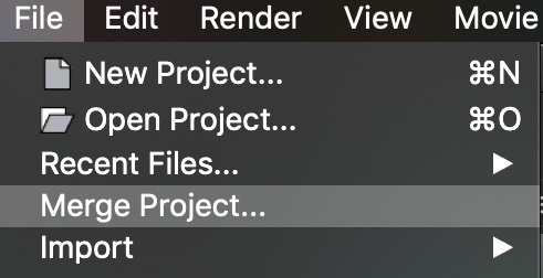
Simply select the Merge Project option from the File menu, and select a project you wish to merge. You can only merge projects that are the same dimensions, aspect ratio and frame length as the shot you are merging into.
NOTE: You cannot merge projects from versions of Mocha earlier than 3.0.0.
Importing Silhouette SFX projects [Mocha Pro Only]
Mocha can also import Silhouette .sfx project files. To import a project:
Open or create a project with matching footage and same dimensions as the Silhouette file. This is important. Your Silhouette project file will need to match the frame rate, dimensions and length of the Mocha project to correctly import.
Go to File → Import → SFX Project Shapes…
Choose a Silhouette sfx project file. If you are in OS X, you may need to navigate inside the sfx package to find the actual project file.
Click Open
The Silhouette project will then convert any Bezier and X-splines to native Mocha splines and appear in the project.
If there are any B-Spline layers in the project, these will not be imported as they are currently not supported.
Tracking Basics
| Some tools, parameters and techniques listed below may not be visible in Essentials mode. To see additional interface elements, switch to Classic mode. See the Layouts section for more information. |
The Planar Tracker
Boris FX’s Planar Tracker technology provides 2D tracking data by tracking planes rather than points.
The key to getting the most out of the Planar Tracker is to learn to find planes of movement in your shot which coincide with the object that you want to track or roto. Sometimes it will be obvious - other times you may have to break your object into different planes of movement. For instance if you were tracking a tabletop, you would want to draw the spline to avoid the flower arrangement in the center of the table — it is not on the same plane and will make your track less accurate.
To select a plane you simply draw a spline around it. You can be fairly loose with your spline — the Planar Tracker is intelligent enough to discard the pixel movement that doesn’t conform to the movement of the majority of the pixels within the shape.
Mocha features two spline types, X-Splines and Bézier splines:
X-Spline
In general X-Splines work better for tracking, especially with perspective motion. We recommend using these splines where possible.

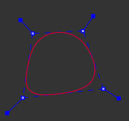
Bézier Spline


Bézier Splines are also very versatile for roto and is the industry spline standard.
CPU vs GPU Tracking
You can choose between a GPU or a CPU tracker in Preferences. By default, GPU is selected, but will fall back to CPU if an operation is not supported by the GPU version.
The GPU option allows you to select any supported graphics card on your system to take on the brunt of the tracking process. The resulting speed improvement is especially noticeable on high resolution footage or when tracking large areas.
The Relationship Between Splines and Tracking Data
One of the most important concepts to understand with the Mocha planar tracking system is that the spline movement is not the tracking data.
It’s best to think of the splines you draw around objects as search areas. Here’s a breakdown of how the tracking works:
By default, any spline you draw is linked to the tracking data of the layer it is currently in. In hierarchical terms, the spline is the child of the track, even if there is no tracking data.
When you begin to track a layer, the area of detail contained within the spline(s) you have drawn will be searched for in the next frame.
If the planar tracker finds the same area in a following frame, it will tell the tracker to move to that point. Because the spline is linked to the track by default, it will also move along with it and the search begins again for the next frame.
To see this relationship, turn on your surface and/or grid in the viewer after you have tracked something. Scrub the timeline and you will see that the grid and surface move with the spline.
Now select all the points of your spline and move it around the viewer. You will notice that the surface/grid will stay in the same place.
This is because the spline is linked to the track, but the track is not linked to the spline. The spline is merely a search area to tell the track where to go next. It is a common misconception that moving the spline while tracking is affecting the movement of the tracking data. It is not. Moving the spline is only telling the tracker to look in a different place and will not directly affect the motion of the tracking.
This makes the tracker very powerful, as you can move and manipulate your spline area around while tracking to avoid problem areas or add more detail for the search.
You can even unlink the spline from the track entirely so that any planar surface passing under the stationary spline area is tracked and you don’t have to move the spline if tracking starts to go off screen.
Selecting an Area to Track
With the Planar Tracker you simply draw a spline around something, as shown with the screen below.

Select one of the spline tools to create a shape around the outside edge of the area you wish to track.
Start creating your shape by clicking onto the screen.
After the third point, the shape will auto-close, but you can continue to add points.
When drawing splines it is best to keep the shape not tight on the edge, but actually give a little space to allow for the high contrast edges to show through, as these provide good tracking data.
Right-click to finish drawing.
If you are using the X-Spline tool you can adjust the handles at each point by pulling them out to create a straight cornered edge, or pull them in to make them more curved. Right clicking a handle will adjust all the handles in the spline at once.
Dealing With Obstructions or Reflective Surfaces
In some cases there are parts of an image that can interfere with the effectiveness of the Planar Tracker. To handle this, you can create an exclusion zone in the area you are tracking.
For instance, in the phone example we are using, there are frames where there are strong reflections on the screen. These reflections can make the track jump. So we need to isolate that area so the tracker ignores it. Here’s how this is done:
Select the initial layer you created.
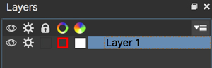
Select the add shape tool to add an additional shape to the current layer, which selects the area you want the tracker to ignore.

Draw this second shape inside the original shape. Note that both splines have the same color, which is an indication that they belong to the same layer. Also you will notice in the Layer Controls panel that you only have a single layer.

By turning on the Mattes button under View Controls you can see the area that will be tracked.
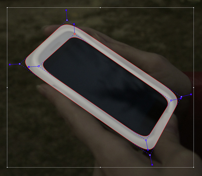
You can also add as many entirely new layers on top of your tracking layer to mask out the layers below.
| The tracking layer uses the matte data of the combined layers you have drawn. This matte is the outer edge of the tracking layer matte minus the inner edge of the layers in front, regardless of feathering. |
This is quite common when moving people, limbs, cars, badgers etc. get in front of the object you are trying to track.
Tracking Parameters
In the Essentials layout, tracking Motion parameters are listed in the Essentials Panel:
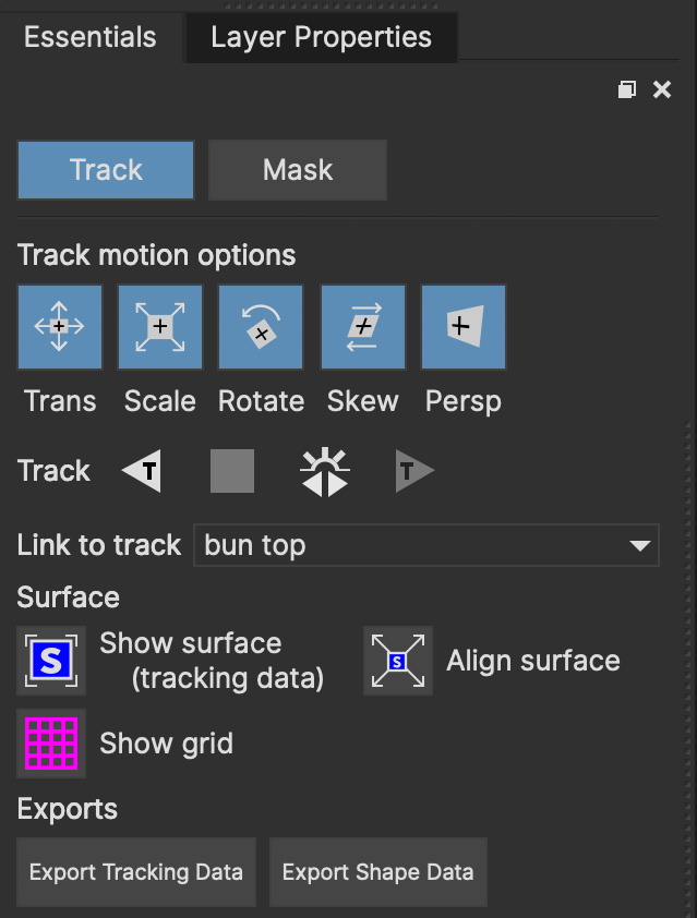
In the Classic layout, detailed tracking parameters can be accessed by selecting the Track tab. On the left hand side of the Track tab, you will see two sections: Motion and Search Area.
| Below, we show the Mocha Pro tracking parameters. Mocha AE and Mocha Vegas will only show the planar tracking parameters: |
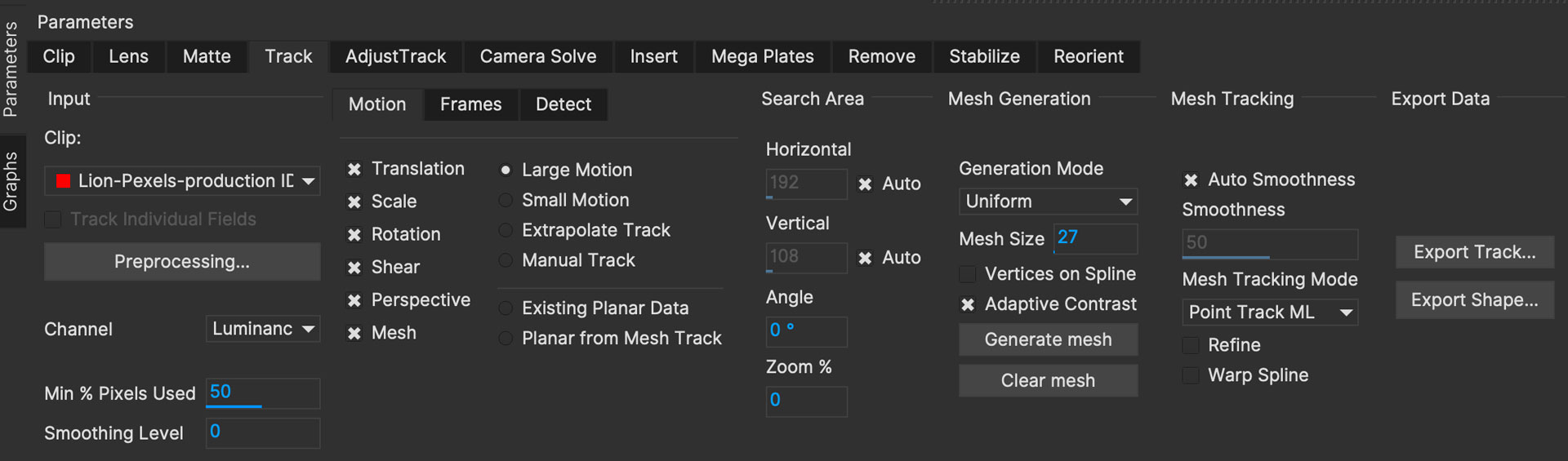
Understanding the parameters section of the Track parameters is vitally important for obtaining good tracks. Here we provide a breakdown of each parameter and how to use it effectively.
Input Clip
This is the clip you are going to track. By default it is the one currently in the viewer.
Preprocessing
| Some features below may only be available in Mocha Pro. Mocha AE and Mocha Vegas will not have this feature. |
This button opens the Preprocessing panel, which has controls for applying non-destructive clip processing for better tracking results:
Any preprocessing adjustments will be automatically previewed while you are adjusting the controls.
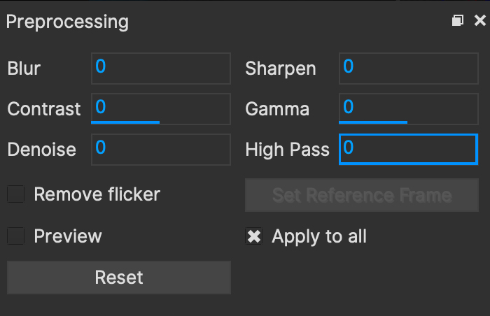
Blur: Blurs the source clip. Useful when there is heavy interference like snow, heavy rain, etc.
Sharpen: Sharpens the source clip. Useful when there is low detail in the image.
Contrast: Contrasts the source clip. Good for low-detail (or low contrast) images
Gamma: Increases the gamma in the image. Note this differs from the gamma view control which does’t affect the clip.
High Pass: Pulls fine details from the image. Enhanced further by using contrast.
Denoise: Reduces noise in the image. Especially useful for very noisy images.
Remove Flicker: Balances flickering footage. This requires using the Reference Frame button
Set Reference Frame: Used with Remove Flicker above. This defines the Reference frame to take the luminance levels to adjust to.
Preview: Permanently previews the preprocessing adjustments
Apply to All: Applies the same preprocessing to all layers. If this is off, the preprocessing only happens to the current layer.
| We recommend trying to track the shot before attempting preprocessing. The planar tracker is very robust and will often track through many problem areas. |
Input Channel
When tracking, Mocha looks at contrast for detail. The input channel determines where to look for that contrast.
Luminance looks for contrast in the light and dark of the image
Auto Channel looks for contrast in one of the color channels.
Red, Green and Blue channels look only in that one color channel for the detail.
By default, Luminance does a good job. If you have low-luminance footage or you are not getting a good track, try one of the color channels or Auto Channel.
Min % Pixels Used
One of the most important parameters to look at for tracking.
By default, the minimum percentage of pixels used is dynamic. When you draw a shape, Mocha tries to determine the optimal amount of pixels to look for in order to speed up tracking. If you draw a very large shape, the percentage will be low. If you draw a small shape, the percentage will be high.
In many cases, the cause of a drifting or slipping track is a low percentage of pixels. If you want a more solid and accurate track, try setting the Min % Pixels Used value to a higher amount. Keep in mind however that a larger percentage of pixels can mean a slower track.
Smoothing Level
This value blurs the input clip before it is tracked. This can be useful when there is a lot of severe noise in the clip. It is left at zero by default.
Motion
These parameters control what motion you are looking for when you track:
Translation: The position of the object
Scale: Whether the object gets larger or smaller
Rotation: The angle of rotation of the object
Shear: How the object is skewing relative to the camera
Perspective: How the object is moving in perspective relative to the camera
Mesh (Mocha Pro Only): Movement within the overall plane, such as distortion, warp etc.
The main difference between shear and perspective is the relative motion. Shear is defined as the object warping in only two corners, whereas perspective is most often needed where the object is rotating away from the viewer significantly in space.
As an example, if someone is walking towards you, their torso would be showing shear as it rotates slightly back and forth from your point of view.
The front of a truck turning a corner in front of you would be showing significant perspective change.
Large Motion: This is the default. It searches for motion and optimizes the track as it goes. Small Motion is also applied when you choose Large Motion.
Small Motion: This only optimizes. You would use Small Motion if there were very subtle changes in the movement of the object you are tracking.
Manual Tracking: This is only necessary to use when the object you are tracking is completely obscured or becomes untrackable. Usually used when you need to make some adjustments to complete the rest of the automated tracking successfully.
Extrapolate Track: Create tracking data based on the motion of the previously tracked keys. This is useful for filling in with estimated motion when you do not have a trackable area or your layer is going off the edge of the image. This works for both planar and mesh tracks.
Existing Planar Data (Mocha Pro Only): This is only used when you want to add Mesh tracking to an existing planar track.
Planar from Mesh Track: Used in combination with PowerMesh to convert the mesh tracking data to planar data. See PowerMesh and Mesh Tracking for more details.
| Extrapolate Track is an estimate only based on the motion of the previous tracked keys for planar and PowerMesh tracks. You need existing tracked data in order to use Extrapolate Track effectively. |
Frames (Mocha Pro Only)
This subtab is for handling frames you need to skip over due to problems, or to step at regular intervals.
Step
The Step field lets you define what frame interval to track with, with the first frame always being tracked as a starting point.
The default is 1, which will track every frame. A value 2 will only track every second frame after the first frame, a value of 3 will only track every third frame and so on.
For those working with stepped or stop motion, you may also want to set your keyframes to constant.
See Keyframe Controls for more information about setting the keyframe type from Linear to Constant.
Skip
The Skip field will let you skip frames or ranges of frames entirely. This is helpful if there is bad or untrackable data on some frames.
Entering a value of 5 for example will skip over frame 5 when tracking.
Entering a value of 5-20 will skip all frames from 5 to 20 inclusive.
| Skipped and stepped frames will leave empty tracking data keys on those frames. Motion will be interpolated between the gaps. |
Search Area
This defines ranges for the tracker to search within
Horizontal/Vertical: The distance of pixels in the footage to search for the next object position. This is set to Auto by default.
Angle: If you have a fast rotating object, like a wheel, you can set an angle of rotation to help the tracker to lock onto the detail correctly. The tracker will handle a small amount of rotation, less than 10º per frame, with Angle set to zero.
Zoom: If you have a fast zoom, you can add a percentage value here to help the tracker. Again, the tracker will still handle a small amount of zoom with this set to zero.
Visualising Search Areas
If you want to see the extent of the horizontal and vertical search area, you can turn on a matte to view the boundaries.
To turn on the search area matte:
Press and hold the
Show Layer Mattesbutton in the View Controls or selectView | Mattesfrom the menuSelect
Selected Search Areasfrom the sub-menuIf the matte view is not already on, click the
Show Layer Mattesbutton to turn on matte view.
You should now see an area around the spline that represents the extent to which Mocha will look for the object in the next frame.
The Selected Search Area view is a visual guide only and has no impact on track mattes or roto. |
Tracking the Spline
Before performing the actual track, adjust the settings depending on the movement in the clip.
Track the plane selected by pressing the Track Forwards or the Track Forwards and Backwards button on the right-hand side of the transport controls section.
Stop the track and adjust the shape if it doesn’t seem to be tracking properly. You may keyframe the spline shape so that it tracks only the planar region of a shape by adjusting the shape and hitting Add Key in the keyframe controls menu. Keep in mind that no initial keyframe is set until you first hit Add Key or move a point with Auto-Key turned on.
Checking Your Track
The spline should be tracked in addition to the clip being cached to RAM. You can play it back and get an idea as to how the track went. F
eel free to change the playback mode in the transport controls to loop or ping-pong your track.
Another trick you can do to check your track is hit the Stabilize button in the View Controls.

Turning on Stabilize will lock the tracked item in place, moving the image to compensate. In the track module, stabilize view is a preview mode to check your track. Actual stabilization output is handled by the Stabilize Module, explained in the Stabilize Overview chapter.
The Surface
You can check the accuracy of your planar track by turning on the Surface (the dark blue rectangle) and Grid overlay in the Essentials panel or the toolbar:

Drag the inner corners of the Surface to match the perspective of your tracked plane.
Drag the edges of the Surface to adjust them along the matched perspective
Drag the points in the middle of the edges to scale horizontally or vertically
Click and drag the outer corners to rotate the Surface
Hold SHIFT and drag a corner to scale uniformly.
If you play the clip, you should see the surface or grid line up perfectly with the plane you tracked.
| The Surface and Grid have no keyframes; they are simply guides that let you check the accuracy of your track. Note that the position of the Surface WILL affect the exported tracking data, so you MUST position the corners of the Surface before exporting tracking data. |
Click on the Surface button in the Essentials panel or the toolbar.
When you turn on the surface you will see the blue box that represents the 4 points of the corner-pin. Right now you will see that it is not lined up with the screen.

As described above, by selecting each corner one at a time you can adjust the surface area to cover the area of the screen,
or you can use the middle points to scale and the outer corners to rotate.
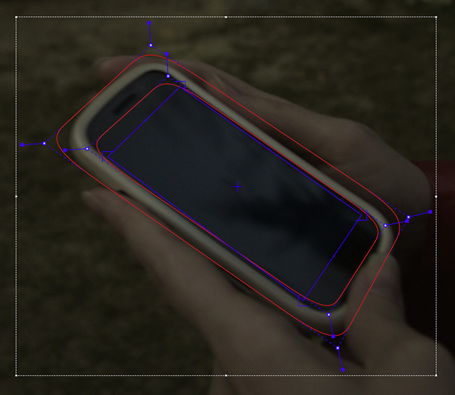
The Grid overlay should line up with the plane you’re tracking and move with it as you cycle through the clip.
You can change the density and scale of the grid by adjusting the values in View | Viewer Preferences:
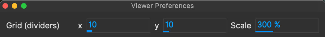
The grid overlay can give you a quick representation of the accuracy of the track.
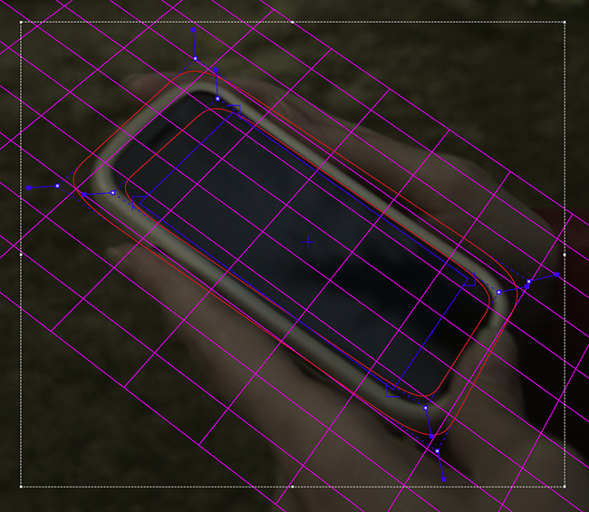
The Trace feature allows you to see the position of the planar corners over time. Skip allows you to work with only every nth frame, useful on particularly long roto shots where the movement is predictable.

| When you track a layer, the mattes of any active layers above the layer itself are subtracted from the matte of the layer and hence influence the area being tracked. To keep your tracking predictable, it is recommended that you keep your tracking layers on the top of the stack unless you specifically wish to use other layers to subtract from the tracking area of layers beneath it. |
To monitor what the tracker "sees" as a tracking area, select the Track Matte button in the view control.
The Surface Right-Click Menu
You can modify aspects of the surface by right-clicking anywhere on the edges or the centre point.

Set Ratio: This submenu allows setting of predefined ratios or custom ratios:
Source: Sets the current surface to the same ratio as the source footage
Insert: Sets the current surface to the same ratio as the insert clip
16:9, 4:3, 2:1: Sets the surface to these commonly used ratio types
Custom…: This brings up an entry field so you can define your own ratio, either in dot format (e.g 1.4) or colon format (eg. 16:9)
Swap: Swaps the width and height of the surface.
Align: This is the same control as the Align Surface tool button in the Toolbar. It will set the size of the surface to fit the dimensions of the tracked footage.
Hide: Hides the surface. To turn it back on you will need to toggle the view from the toolbar.
Reset: Resets the surface back to the dimensions of the spline area. If more than one spline exists in the layer, it will reset to the collective area of all splines.
Hide Insert: Hides the insert clip inside the Surface without turning off Preview. Toggle to turn the insert back on.
| Changing ratios is performed on the currently distorted state, so will be set as close to the correct ratio as possible. |
Redoing or Deleting Tracking Keyframes
If you want to start a section of tracking from scratch, you can just re-track the area without clearing keyframes.
However if you’d prefer to delete keyframes you have multiple methods.
Clear from the Timeline
You can use the clearing buttons on the righthand side of the timeline to delete keyframes as a batch.
| Delete All Keyframes: Deletes all keyframes on the timeline for the selected layer |
| Delete All Forward Keyframes: Deletes all keyframes on the timeline forward from the playhead for the selected layer |
| Delete All Backward Keyframes: Deletes all keyframes on the timeline backward from the playhead for the selected layer |
All keyframes on the Mocha timeline are contextual, i.e. what you select in Mocha updates the timeline to show the keyframes for that selection.
For example, if you have a spline selected, Mocha will show the spline keyframes. If you select a keyframable parameter, it will show those keyframes and so on.
For tracking, the keys are hidden unless you expose them using the Manual radio button in the Motion section of the tracking parameters.
To correctly delete tracking keyframes this way:
Click on the
Manualradio button in the Motion section of the track parametersPosition your playhead where you want to clear the keys (If you are clearing all keys you don’t need to do this)
Click the corresponding delete button to clear tracking keyframes
Click the
Large Motionradio button to take the tracking out of Manual mode again.
| If you don’t want to make a keyframe for the Motion selection, turn on the Uberey button before you switch modes. |
Clear from the Dopesheet
The alternative method for clearing keys is to open the dopedheet and delete the keys from there.
To correctly delete tracking keyframes this way:
Switch to the Dopesheet
Locate the layer you want to clear keys from
Twirl down the Layer tree
Twirl Down the
TracksectionSelect all group level keys (these are the hollow keys) of the track section you want to delete
Press the delete key
You will see the blue section of the keys you deleted clear in the timeline.
Importing Mattes
| This feature is only available in Mocha Pro |
There may be instances where you have already created mattes for one or more objects in the shot, for example using a keyer or another roto tool that would help you isolate areas to track.
You can import such mattes by creating a new layer and then using the Matte Clip setting under Layer Properties to assign it to the layer.
Offsetting Matte clips
If your matte clip has a different frame offset to the source clip, you can change its clip offset:
Import your matte clip to the selected layer
Go to the Clip module
Select the layer matte clip in the clip selector under General
In the Timeline section of the clip module, change the
Clip frame offsetto the same offset as the footage clip
For example, if your source clip starts at 1001 and your matte clip starts at 1, you can change the Clip frame offset of the matte clip to 1001 to make it line up correctly.
This should then line up the matte clip to the source clip.
Merging Tracks
| This feature is only available in Mocha Pro |
Sometimes when you’re dealing with a difficult shot it’s easier to break the tracking into multiple layers.
If you want to combine these tracks together you can do so with the Merge Layer Tracks option.
Merge Layer Tracks appears as a button under the layer controls, but is also available as a menu option under the Edit menu and the Actions menu.
Track merging creates a new layer with the merged keys.
This happens in a top-to-bottom priority, meaning that tracking keys in the topmost layer of the selection will always be copied,
then the next layer will merge any keys that should fill gaps missing from the previous layer and so on until all layers are merged.
| Merging a combination of layers that have gaps in the tracking data may produce unstable results. |
To use Merge tracks:
Select the layers you want to merge. The layer tracks should be on areas with similar planar movement, especially if merging perspective or shear tracks.
Click the
Merge Layer Tracksbutton in layer controls
A new layer will then be created with the combined layers.
Keyframe Controls
If you want to change the way keyframing is handled in the project, you need to adjust the keyframe controls.
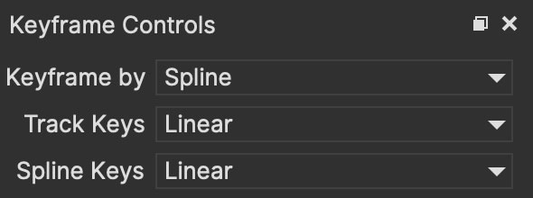
Keyframe By
This dropdown controls how keyframes are handled when animating splines:
Spline: Keyframe all points in the spline on adjustment
Points: Keyframe only the current point you are moving in the spline.
The recommended default is "Spline" as this keyframes all points when you manipulate any point on a spline.
This makes it much easier to keep track of where in time you have animated the layer.
Track Keys and Spline Keys
When working on certain shots, especially with stop motion animation, you may not want motion to transition smoothly between keyframes.
The Track Keys and Spline Keys allow you to define:
Linear: Interpolate motion in a linear fashion between keys
Constant: Do not interpolate between keys and hold the motion until the next keyframe.
Tips for Tracking
Scrub your timeline
When starting a new project, go through your footage a few times to see what your best options are for tracking. You will save yourself a lot of time by making note of obstructions and possible problem areas in advance.
Use edges
When tracking surfaces you will usually get a much better track if you include the edges and not just the interior of an object. This is because Mocha can define the difference between the background and the foreground and lock on better.
For example, if you are tracking a greenscreen, it is better to draw your shape around the entire screen rather than just the internal tracking markers. In some cases this means you can avoid tracking markers altogether and save time on cleanup later.
When in doubt, ramp up your pixels
You can quite often get a great result with default settings, but if you’re getting a lot of drift, try setting the Min % Pixels Used value higher. The processing can be slower, but you will usually get a much more solid track.
Draw more shapes
Remember you are not limited to one shape in a layer. Use a combination of shapes to add further areas or cut holes in existing areas to maximize your search. If necessary, make an additional layer to track and mask out foreground obstructions before tracking the object you need.
Use the grid while tracking
It’s common to use the surface and the grid to line up your corners after you track, but it can be much more advantageous to set up your surface before you track and leave the grid on to watch for any subtle drift while you are tracking. This way you can stop your track early to fix any issues and spend less time trying to find them later.
Track from the largest, clearest point
In order for Mocha to keep the best possible track, it is usually best to scrub through the timeline and find the largest and clearest area to begin tracking from, draw your shape there, then use backwards and forward tracking from that point.
For example, if you have a shot of sign coming toward you down a freeway, it is usually better to start at the end of the clip where the sign is largest, draw your shape and track backwards, rather than start from the beginning of the clip.
A planar surface does not necessarily have to be flat
We have a Planar Tracker which specifically tracks planes of motion, but this is not limited to tables, walls and other flat objects.
Distant background is considered flat by the camera where there is no parallax. Faces can be tracked very successfully around the eyes and bridge of the nose. Rocky ground, rumpled cushions, clumps of bushes, human torsos and curved car bodies are all good candidates. The key is low parallax or no obvious moving depth.
When in doubt, try quickly tracking an area to see if it will work, as you can quite often trick the planar tracker into thinking something is planar.
In the end, there is no magic bullet
Mocha is a very flexible tracker and will save a lot of time, but you will eventually run into a piece of footage that just will not track. Large or continuous obstructions, extreme blur, low contrast details and sudden flashes can all cause drift or untrackable situations.
If something just isn’t tracking no matter what you try, consider using Mocha to track as much as possible then move to manual work. You can often get a lot more done fixing shots by hand or using AdjustTrack in Mocha rather than trying to tweak your shapes and parameters over and over again to get everything done automatically.
PowerMesh and Mesh Tracking
PowerMesh is designed to help track non-planar surfaces. This is for both rigid and non-rigid surfaces that would otherwise be impossible to track with a regular planar tracker.
Rather than taking an optical flow approach (which can be slow to render and produce cumbersome files), we use a subsurface planar approach which is much faster to generate and track.
There is also a fast machine learning model that can help track meshes in more difficult shots.
| PowerMesh tracking currently does not support Stereo |
Mesh Generation
To track a mesh, you first need to generate one.
The initial process is as follows:
Draw a layer around the area you want to track

Choose the planar tracking parameters (translation, rotation, scale, shear and/or perspective)
Then choose the “Mesh” parameter

An initial Mesh is generated.
![]()
Then you can refine your PowerMesh with the following parameters.
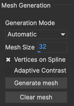
Generation Mode
This dropdown contains two options:
Automatic: This determines the best mesh to use based on image information contained in the layer. Automatic is best paired with “Adaptive Contrast” to get the most detail.
Uniform: Generates a uniform square mesh insead of building based on the existing image.
Mesh Size
Mesh Size is the distance between vertices in pixels.
This means that the smaller the Mesh Size, the more potential mesh faces you will have. The larger the Mesh Size, the larger the faces and the less faces you will have.
A good starting point for Mesh Size is 32 for a HD or 4K image.
Vertices on Spline
This option makes sure the PowerMesh is generated to the boundaries of your layer spline, rather than just over the most interesting detail within it.
For uniform meshes, this option makes sure at least part of the mesh is overlapping the spline.
Adaptive Contrast
Adaptive Contrast boosts details in the underlying image to help the Automatic mesh generate the most useful vertices. Use with care! Sometimes you don’t want too much mesh detail.
Generate Mesh
This button generates the Mesh. Click it every time you change a Mesh generation parameter.
Clear Mesh
This button clears the Mesh from the layer.
Mesh Tracking
Once you have generated your mesh and you’re happy with it, you can move on to tracking.
The Mesh tracker first uses the standard planar tracking per frame and then applies the sub-planar track with the mesh.
Any mesh faces that fall outside of the spline or the image boundary are ignored. Those mesh faces become rigid and try to follow along with the existing mesh.
To perform a Mesh track:
Generate a mesh using the method and parameters listed above
Choose the planar motion parameters you want to use
Choose the Mesh Tracking parameters
Track forwards or backwards as needed
Note that choosing the Planar motion parameters is important. For example:
If the region you are tracking has significant perspective distortion, turn on Perspective
If the region doesn’t have much perspective shift, use Shear.
If the region doesn’t have much planar distortion, choose the lower order motion parameters only (Translation, rotation, scale)
The Mesh Tracking parameters help control how Mocha approaches the organic surface.
![]()
Auto Smoothness
Turning this on tells Mocha to guess the amount of smoothness to apply to the Mesh track. See “Smoothness” below.
Smoothness
Also referred to as “Rigidity”, this value determines the amount of smoothness to apply to the Mesh when tracking.
A high smoothness is like applying starch to your Mesh. It will follow the planar track more rigidly and not distort as much.
A low smoothness will follow the subsurface movement more directly and distort the mesh more. In short, you will get more “wobble”.
As a general guideline, we recommend setting a lower smoothness for very warped or wobbly movement and a higher smoothness for more rigid objects that still have some distortion.
For example:
Faces: This varies, but a smoothness of 50 is about the right amount to balance facial muscles vs general face planes.
Liquid: A low smoothness (20-40) works well
Cloth: Variable depending on the stiffness of the material
Mesh Tracking Mode
This dropdown lets you select what type of tracking to use with PowerMesh:
Planar: Useful for fast tracking of dense meshes
Point Track ML: Best used for difficult or turning shots
| Point Track ML currently has an upper limit on how many mesh points it can track. Try to restrict your meshes to a value at or below 500 vertices. |
Refine
This option is tied to Point Track ML, which you can select in the Mesh Tracking Mode above.Refine performs a secondary step in Point Track ML where it uses the full resolution of the footage to find more details for the track.
Warp Spline
This option deforms the spline shape to match the movement of the Mesh while tracking. This is useful so that you don’t have to worry about animating the shape to keep the mesh inside the bounds of the spline.
As an added bonus, this also means it greatly reduces the keyframes needed to rotoscope an organic object.
Mesh Tracking with Existing Planar Data
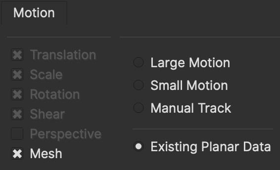
If you want to track a PowerMesh using a layer you have only tracked with planar tracking (Translation, Rotation, Scale, Shear, and/or Perspective)
you can do so by using the "Existing Planar Data" radio button in the Motion options.
This avoids you having to redo the entire track from scratch with the Mesh.
This option is only available if you have selected the Mesh motion parameter.
To use Existing Planar Data:
Track a layer using some form of planar motion type (Translation, Rotation, Scale, Shear, and/or Perspective)
Create a new layer
In the new layer, go to Layer properties and choose "Link to track" and select your tracked layer
In the new layer, select "Mesh" and adjust your mesh parameters (see above)
Select "Existing Planar Data" from the motion options
Track forwards.
You can also do this for the same layer you are on without creating a new layer. Any planar tracked layer can have the Mesh applied later
and then simply be retracked using "Existing Planar Data".
Mesh Tracking with Planar from Mesh Track
When using Point Track ML as the PowerMesh tracking mode, it can often recover well from turning or obscured surfaces.
In some cases it will even provide a more stable result than the regular planar track.
In these cases, we recommend tracking Meshes using Planar from Mesh Track in the motion settings.
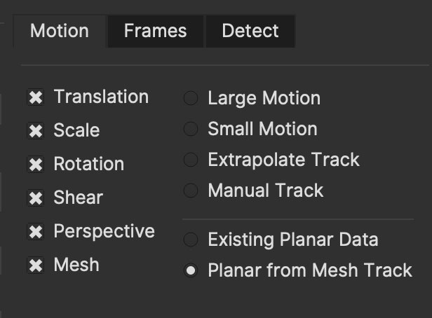
This will override the regular planar track and convert the motion of the mesh to planar data instead.
Once completed, you can also delete the mesh if it is no longer needed and the planar data will remain intact.
Edit Track Mesh
The Edit Track Mesh button is in the Toolbar at the top of the Mocha interface.

Selecting this turns on subselection in your mesh and you can move or delete vertices either before or after you have tracked the mesh.
To get out of Edit mode, click the normal selection tool.
After Tracking, You can animate the tracked mesh manually to fix points or make your preferred adjustments.
Animated meshes are keyframed for the whole set of vertices, rather than individual points. This makes it easier to keyframe states over time, similar to the spline default animation mode.
Add Vertex

This tool appears when in Edit Mesh mode. When Add Vertex is on, click any Mesh edge to add a new vertex. A new edge will appear joining the created vertex and the vertex opposite.
Using Mesh Falloff to Adjust Clusters of Points
Normally adjusting Mesh points is done by moving selections of vertices or carefully moving individual ones.
An alternative approach is to use the falloff tool to move areas of vertices in a Mesh all at once with a gradient of strength.
With the Edit Track Mesh tool active, you can click the falloff icon to activate the Mesh selection radius.
In order to use Mesh falloff, you must have Edit Track Mesh selected, otherwise falloff will only affect splines. |
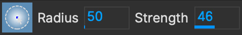
Mesh falloff is adjustable via a field in the Falloff panel:
Radius: Adjusts the size of the affected area
Strength Adjusts the strength of the falloff. At 100% all points within the radius are moved the same amount as the selected point.
You can use Ctrl/CMD and Left-Dragging to adjust the size of the Radius. Similarly, you can adjust the strength by holding Ctrl/CMD+Shift and Left-Dragging.
Adjustments are visualised by a red gradient, but this turns off while using the tool on Mesh points.

Any points under the circle will be affected.
Exporting Meshes or Mesh Warped Splines
Using PowerMesh, you can export:
Mesh-warped splines (or render their mattes): Export as normal for Shape data.
After Effects nulls (Adobe plugin only): In the Adobe plugin, there is a new section called "PowerMesh". Use this section to create nulls from selected layers. See Creating PowerMesh Nulls for more details.
Alembic tracking data as a mesh: The exports from the "Tracking Data" export options. Alembic is supported across many hosts. The data format includes the PowerMesh and a camera that fits to the source footage. See Exporting to Alembic for more details.
Nuke Mesh Tracker: This will export a single Tracker node for Nuke that contains a single tracker point for every vertex in the PowerMesh.
Tips for Mesh Tracking
Blue mesh faces
When tracking, if one of your mesh faces turns blue, this means the face has become flipped, normally because the area you are tracking has turned away from the camera.
Use more than one contour
You can use more than one contour to cut holes in the mesh generation. This is helpful if you want to ignore details in a surface, such as teeth in a mouth region or a tattoo that is taking up too much of the mesh detail.
Face Detection
The Track module also includes a subtab called "Detect" which contains tools for face detection in your scene.
Detecting Faces
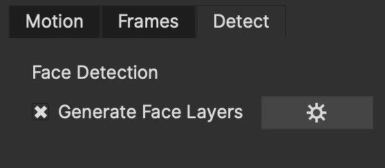
To detect faces in your scene, the process is very straightforward:
Go to the
Detectsubtab in the Track moduleCheck the
Generate Face LayerscheckboxTrack forwards or backwards as needed
You can also run the same process in the Essentials panel.
Detecting from the Essentials panel will automatically Face Detect without needing to turn on the checkbox in the Track module:
Mocha will then create a new Faces group in the Layer list and track any faces in the scene using simple ellipses:

| While the detect process is generating tracking data, it is not using the standard Mocha planar tracking, and therefore may not have the same level of accuracy as a standard Mocha track. |
The ellipses will follow the translation, scale, rotation and skew of the face and will focus on the main features.
For example in this shot, the broad identifying features are covered, but the spline won’t exactly match the contours of the face:
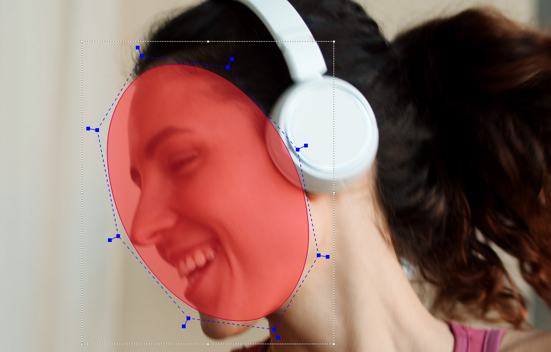
Face Persistence
Currently Mocha does not have face persistence, so multiple layers may be created for the same face.
If a face is obscured or goes out of the shot, the face layer will be cut off to its layer range (in/out points).
If the face reappears, a new layer will be created at that frame.
False Positives
In some cases, the face detection will identify an area that isn’t actually a face.
If this happens, simply delete offending layer.
Exporting Face Layers
Faces are like any other layer with spline and tracking data so can be exported the same.
You can choose to render the mattes to disk or via the plugin or export them as data.
Most shape data formats will support the in/out ranges of each face either by an active range or an animated opacity keyframe.
Stereo Tracking
| Please note that stereo features is only available in Mocha Pro |
Tracking in Stereo is very similar to tracking in Mono. In fact we’ve designed it specifically to be as transparent as possible to those used to the standard Mono workflow.
Select your hero view (By default this is the Left view)
Draw your shape as you would normally in mono mode (See Mocha User Guide for an introduction to mono Mocha tracking techniques)
Press the "Operate in all views" button on the right side of the tracking buttons.
Select your tracking parameters as normal
Track forwards (and/or backwards if required).

If you now switch between Left and Right views you will see the Right view has automatically been tracked and offset from the Left view.
Manual Stereo Offset
If you would prefer to only track and work with the Hero view initially then offset your data manually, you can also do this using the Stereo Offset tab in Track.
Select your hero view (By default this is the Left view)
Draw your shape as you would normally in mono mode (See Mocha User Guide for an introduction to mono Mocha tracking techniques)
Make sure the "Track in all views" button on the right side of the tracking buttons is switched off.
Select your tracking parameters as normal
Track forwards (and/or backwards if required).
This will only track the current view you are on. If you switch to the other view you will see the layer still moves with the track, but is not offset like when you do an all-views track.
You can then use the Stereo Offset parameters in the Track module to offset your view.

If you decide later that you want to track the non-hero view, you can do so by selecting the non-tracked view then track as normal.
You have the following options in the Stereo Offset tab (see above) when tracking another view based on the hero view:
Track from other views: This will reference the existing track to help track and correctly offset the current view.
Track this view: This will reference the current view to get the tracking information.
Note that by default these are both selected to give best results. If you only use Track this view and not Track from other views, the current view will be tracked independently of the hero view and will not offset.
You can also open existing mono projects that have additional views and track them without having to manually offset. Just set the mono project to Multiview in the Project Settings and add the additional footage streams to the clip.
Offset Frame Tracking
For simpler tracks, you can also do a technique called "Offset Frame Tracking" which is a combined stereo track and hero track.
Select your hero view (By default this is the Left view)
Draw your shape as you would normally in mono mode (See Mocha User Guide for an introduction to mono Mocha tracking techniques)
Turn ON the "Operate in all views" button on the right side of the tracking buttons.
Select your tracking parameters as normal
Track ONE frame forwards (You can track more if you prefer, but only one is required)
Check the track in both views to verify the stereo offset has occurred correctly
Turn OFF the the "Operate in all views" button on the right side of the tracking buttons.
Continue tracking forwards with just the hero view
If your initial stereo track was offset correctly, that offset will then carry onwards through the rest of the track.
Keep in mind that things like convergence and disparity in the moving stereo image may not work accurately in this scenario,
but it will increase performance of the process because you only have to track one eye.
You can also then apply additional manual stereo offsets as described in the manual offset section above.
AdjustTrack
Overview
There will be times when tracks can drift due to lack of detail or introduction of small obstructions. When this occurs, manual refinements can be made by using the AdjustTrack tool.
AdjustTrack is primarily used for eradicating drift by adjusting reference points to generate keyframable data to compensate. It is generally not practical to use it to remove jitter.
To achieve an adjusted track you would ideally line up the surface area where you want to place your insert or lock down your roto.
In situations where you don’t require an insertion you could place the corners of the surface area in distinctive locations.
The Transform AdjustTrack is designed to be an easier user experience from the Classic AdjustTrack (see below) by removing the need to use the surface as your alignment tool.
In Transform AdjustTrack you can adjust based on specific transforms with as many reference points as you require over time.

Setting up reference points
You can set reference points either as a template for the kind of adjustment you want, or add them yourself as needed.
| We recommend turning off the splines view (i.e 'Show Layer Outlines') during adjusting the track so you can see the adjustment of points clearly. |

Transform Type
The transform type is used to set up the method of Adjustment you want to use for the shot.
Each checkbox sets a different number of points when you click “Set Points”
Translation: Sets one point for x/y translation
Scale/Rotation: Sets two points to rotate or scale between points. Moving a point toward or away from the other point scales, moving a point at an angle the other causes rotation.
Shear: Sets 3 points for allowing skew/shear adjustment
Perspective: Sets 4 points for full 4-point corner-pin style perspective adjustment.
Note that the Transform selection works in a similar way to the Motion type in the Track module. When you select a motion type further down the list, it will automatically select the ones above it in order for the tracking keyframes to be adjusted predictably.
You can opt to turn off the default-selected transform types later if you need to do a specific adjustment.
After you have chosen the type, click 'Set points' to create the points. You can then adjust the reference points (see below).

Reference Points
You can add more points to your adjustment as required. Each point contributes to the adjustment of the plane based on the position of the other points.
You can select between the points using the cursor or cycle using the select <> buttons.
Position your points on easily identifiable areas
Once you are happy with the position of the points, click “Set Reference Frame” to define a frame to look to when adjusting forwards or backwards from that point.

Adjusting points
Once you are happy with the points positions and have set a reference frame, you can start moving back and forth on the timeline adjusting the points for drift.
Right-clicking a point selects all points or you can shift-click individual points and can move them as one.
Take note of the Transform type when moving points, as the Transform type affects how points adjust the track.
By default, for your initial set of points, each point adjustment sets a key frame for every other point in the shot to avoid unwanted distortions.

You can see the original reference frame for the selected point in the zoom window in the upper left of the viewer and the current frame in the window below that.
| An adjustment point only affects the track within the bounds of its own keyframes. Outside that keyframe range it stops adjusting the track. See Adjustment Point Lifespan |
You can then keep adjusting the points over the timeline until all drift is corrected.
Point Arrows and Keyframe Direction
You’ll notice as you make keyframes for your points that they have different arrow symbols in the viewer. These help you determine what points have been keyframed and if there are other keyframes in the timeline for that point.
If there are point keyframes to the left, right or both sides of the current frame, arrows will appear to indicate the direction they are in.
Here’s what these symbols mean:
| Reference Point: An initially placed reference frame point with no adjustment keyframes. |
| Reference Point with Keyframes: A reference frame that has adjustment keyframes. Arrows will point in the direction keyframing has been done on the timeline. If there are keyframes on either side of the reference frame, there will be arrows on both sides. |
| Keyframed Point: A point that has been keyframed. The bracket arrow indicates the keyframing. Closed triangle arrows point in the direction of other keyframes that exist on the timeline for this point. |
| Non-Keyframed Point: A point that has not been keyframed on this frame. The non-bracketed triangle arrows will point to other keyframes for this point on the timeline. |

Adding New Points for Further Adjustment
It’s quite common that one of your AdjustTrack points is going to get obscured, go out of frame or no longer have a usable visual reference in the scene.
This is when you may want to add new points to the adjustment.
You can add as many points as you like to an adjustment over time. Each keyframed point contributes to the adjustment on that frame.
In order to do this effectively however, you need to understand AdjustTrack Transform keyframe ranges.
Adjustment Point Lifespan
Each point in AdjustTrack Transform has what is known as an effective keyframe range. This is the lifespan of the point currently in use.
A point can be moved to contribute to the current adjustment, but that point’s adjustments are only valid between those keyframes.
Any additional keyframes you add to a point further in time forward or backward from the reference point will contribute to the overall adjustment.
Points do not contribute to an adjustment outside of their keyframe range.
What this means is you can add new points further along the timeline that can create adjustments that won’t be affected by the other points.
The point below has a reference point at frame 571 and an adjustment keyframe at 610. This point only affects the track adjustment between these keyframes: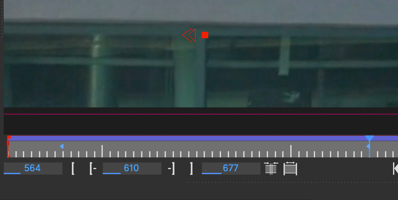
Also note the extra bracket on the arrow on the adjustment point. This tells us we’re currently in the contributing keyframe range of the point.
Creating a New Point as a Replacement Reference
Sometimes a point can no longer contribute to the adjustment.
When you want to add a new point to continue the adjustment, you can create one at the keyframed boundaries of the old point:
Go to a frame in the timeline that is on or outside the keyframe range of the point you are no longer using.
Click "Add New Point" to toggle on the new point tool
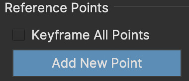
Place the new point at a clear feature location. It will then become a new starting reference point.
Click "Add New Point" again to toggle it off
You will will then want to keyframe points separately to avoid keyframing the old point. See "Keyframing with a New Point" below.
Keyframing with a New Point
By default, all AdjustTrack points are keyframed at the same time with the "Keyframe All Points" option:
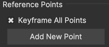
When adjusting new points in a different keyframe range you will want to turn off "Keyframe All Points" or use the Alt+CMD/Ctrl shortcut when altering points.
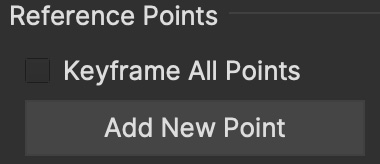
This is important, because continuing to keyframe all points will make the old points still affect the adjustment at that frame in the timeline.
After creating your new point:
Move to a new position in the timeline where there is drift
Turn off "Keyframe All Points" (Or hold down
Alt+CMD/Ctrl)Adjust the new point
Repeat for any points still contributing to the adjustment
Do NOT keyframe the old point. Keyframing an obscured or out of frame point will re-add its position to the adjustment
We recommend locking points when you are no longer using it in the current adjustment range. See Locking Points below.
| Keyframing Adjustment points will cause them contribute the adjustment in that keyframe range. Keep this in mind when going back to older points. |
In this example, the point in the bottom corner is about to go off screen. It’s last adjustment keyframe is on frame 276: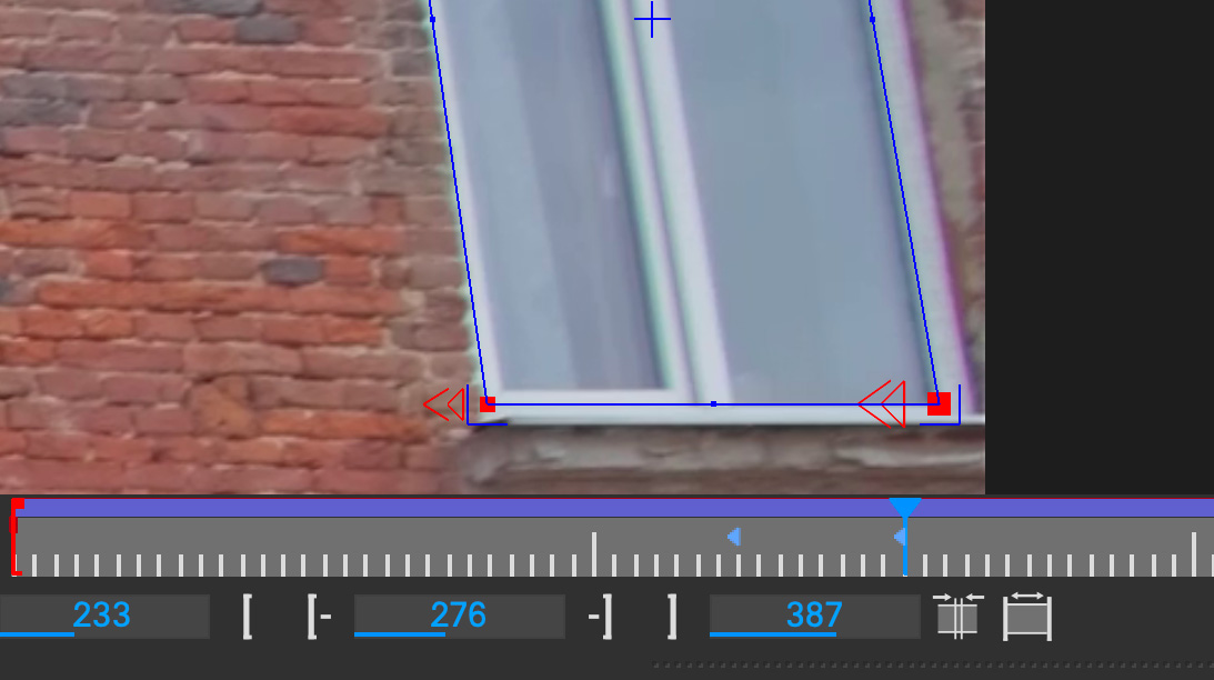
We can create a new reference point at this frame to keep adjusting when the old point goes offscreen. Note that this is on the same frame (276):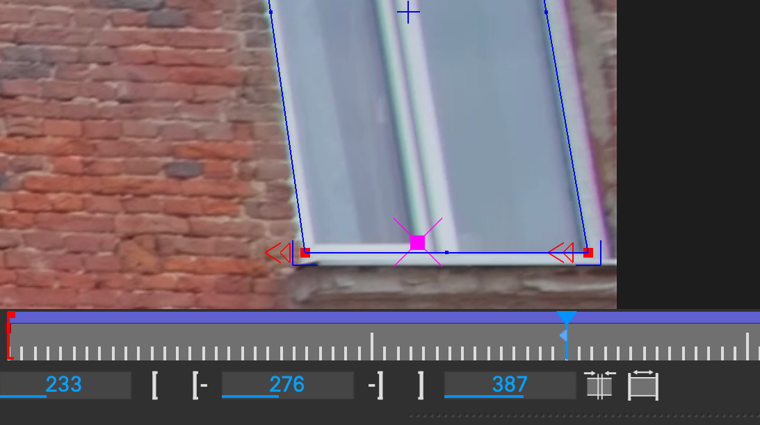
Further along the timeline, the old point is now out of the screen, but we can keyframe the new reference point, making sure we’ve turned off "Keyframe All Points":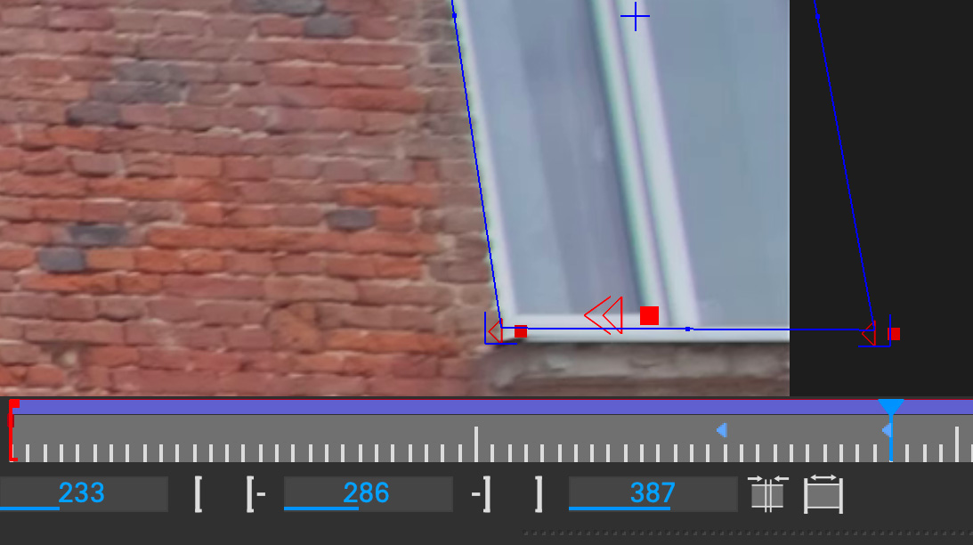
We then adjust any other point we still want to contribute to the adjustment, adding a keyframe for those points. Note the specific keyframing arrow that tells us it’s contributing.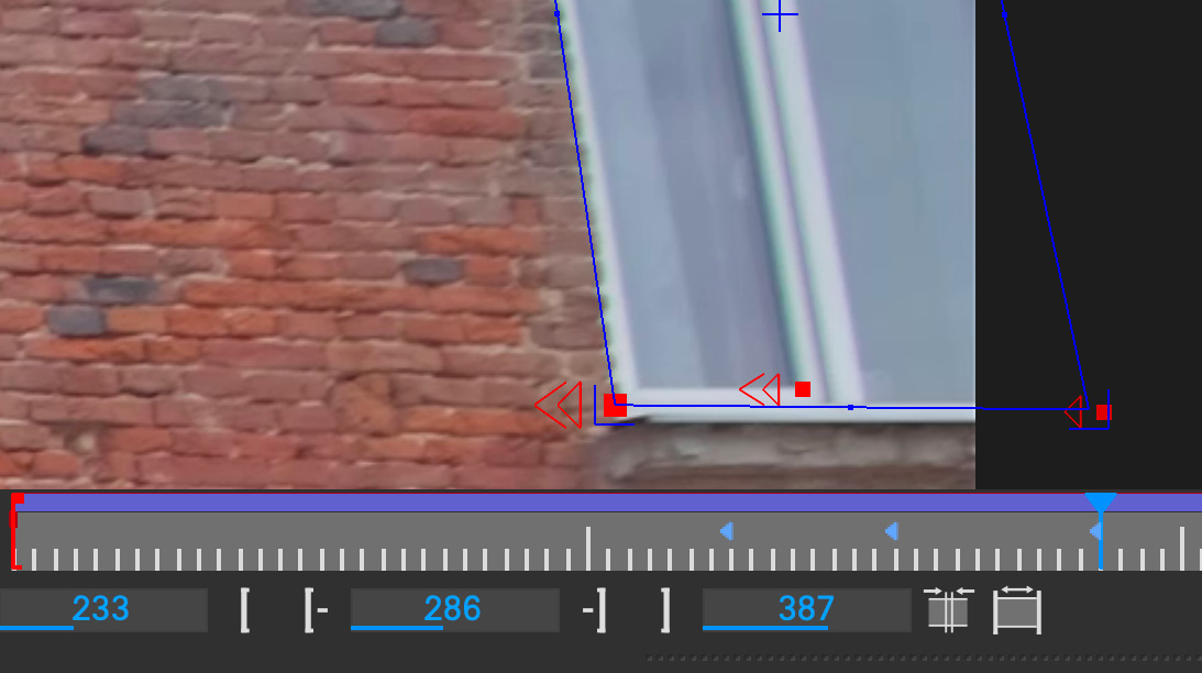
Selecting the old point that is outside the view, we can see it doesn’t have a keyframe on this frame, and so it is not in the adjustment range:
Locking Points
To avoid keyframing reference points by accident, you can lock a point by using the lock icon in the interface:
When a keyframe is locked, it turns gray in the viewer. It can still be selected, but you can no longer keyframe or move the point until you unlock it again.

To unlock a point, just select it and click the lock icon again.
Surface View
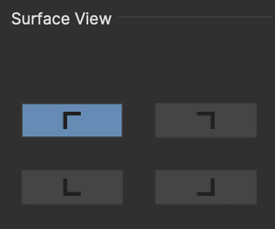
While you are adjusting, you can click one of the “Surface View” corners to see how the surface itself is adjusting to your changes. This is helpful if you are ultimately planning on using the surface as your export area and want to make sure it is still lining up.
Nudge
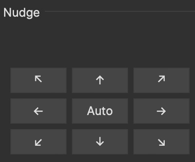
Nudging is used to adjust the track by pixel increments. This helps when adjustments are too subtle to be done by mouse movement.
Each arrow nudges in the indicated direction. You can either click and hold the button or use the shortcut keys to nudge.
The 'Auto' button in the middle of the direction grid tries to guess where the point needs to be.
It can be useful to start with 'Auto' to attempt to place the reference point first, then adjust manually.
Auto Nudge
Auto Nudge takes the 'Auto' action above and lets you use it space adjustments over the whole shot.
If you set 'Auto Step' and define a frame step you can then 'Track' the Auto Nudge using the tracking buttons in the timeline.
Auto Nudge will then nudge the selected reference points at the frame step interval set.
Nudge Type
You can select two types of Auto Nudge:
Planar: The original nudging method
Point Track ML: A machine learning method that provides a lot more options.
Planar Nudge
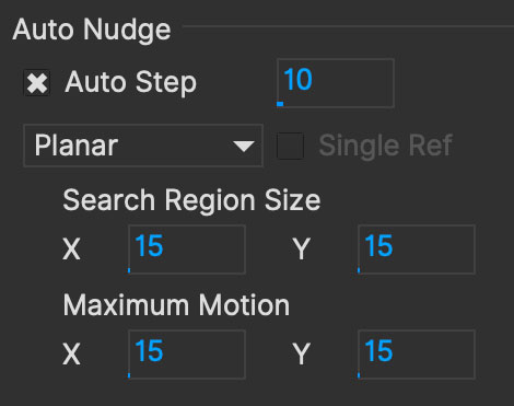
You can define a search area to look for the next point.
The Search Region Size and Maximum Motion fields define how far Auto and Auto Nudge look for the area the point needs to adjust to.
Point Track ML

The Point Track ML approach uses machine learning to help find the drifting point.
This mode can be very helpful if Planar nudge does not give a good result, especially in areas where a drifting point goes out of the image.
This also comes with a range of supporting grid options:
Single Ref: This option means the Point Track ML comparison will only check against the reference frame instead of batches of frames. This can be quicker, but might be less accurate.
Refine Mode: These options allow you to refine the nudge further:
None: No refinement
Per-point: Does a secondary check with every point to further refine the nudge
Image: Does a full-resolution check of the image to refine the point
Support Grids: A series of fields to expand the point into a grid of points for more nudging accuracy:
Point: Adds a grid of points around the selected point
Size: How far apart the support grid is spread for points
Surface: Adds a grid of points inside the surface area
Scale: How much to scale the surface grid
Image: Adds a grid of points across the image
For example, here is a support grid with 3 points around each of the 4 corner reference points on a surface:
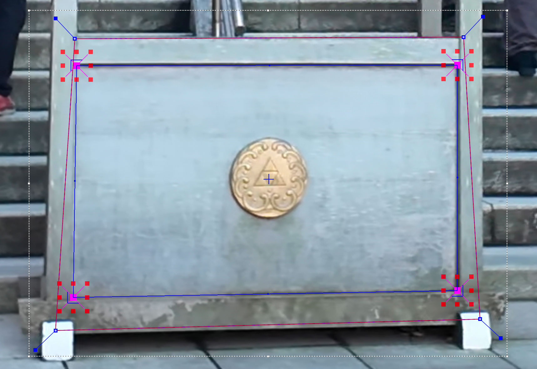
In the example above, the Point value is set to 3 and the Size is set 30. All other support grid fields are left at their default values.
Using these settings, Auto Nudge will check the original point and get assistance from the grid of points around it.
| Auto Nudge is useful for quickly going through a shot to help pace adjustments. It is not recommended to be used as a solution for finishing adjustments. |
Exporting
You can export adjusted tracks as normal via the file menu or via the Track module just like any regular track.
AdjustTrack Classic
We’ve kept the old-style of AdjustTrack for those who prefer to it, or if you are working with legacy projects.
This version of AdjustTrack is primarily used for eradicating drift by utilizing the four-corner surface area to generate keyframable data to compensate. It is generally not practical to use it to remove jitter.
Starting the Track Adjustment
When you have the Surface where you want it to stay locked and are ready to refine the track, flip over into the AdjustTrack module by hitting the AdjustTrack tab.
Then switch to the Classic tab.
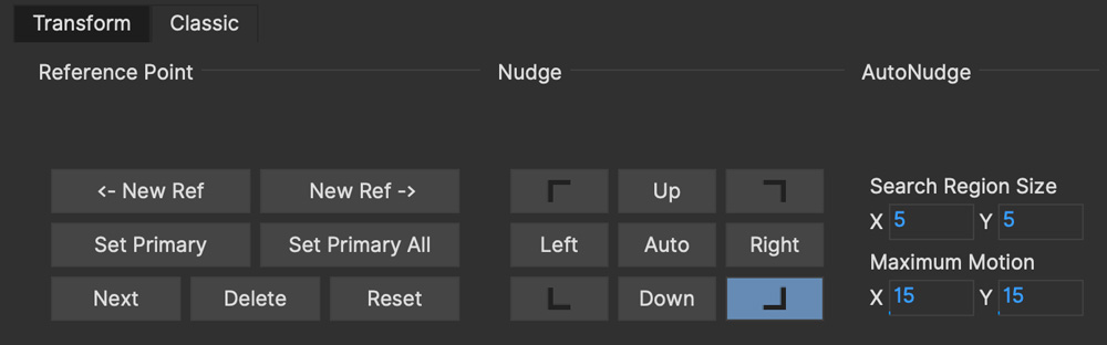
Reference Points
Once you select the Classic AdjustTrack tab, a key frame with four reference points is created.
| You should be on your desired primary frame before selecting the AdjustTrack tab. The reference points can then be positioned on distinctive features, such that any drift in the track can be easily seen and corrected. |
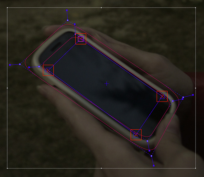
As you play though the sequence you will be able to manually adjust the position of each point as drift occurs.
If your track is spot on, these reference points should line up properly throughout the shot. If you see a Reference Point drifting, that will indicate the track is drifting. Find the frame where the drift is worst and move the Reference Point back to the position it had in the Primary Frame and the track will automatically be adjusted based on your correction.
Reference Point Quality
When you perform an adjust track and you begin to move a newly created reference point, you will notice the dashed lines which connect all of the reference points. These lines change in color to represent the quality of positioning of any given reference point. For best results keep reference points away from one another.
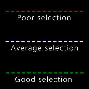
When adjusting the track try to always get at least yellow but shoot for green for a more solid adjust track.
The red lines indicate that this reference point position is a poor choice.

The green lines indicate that this reference point position is a good choice.

AdjustTrack with More than Four Reference Points
Often there are times where your reference points are either obscured or exit frame. In AdjustTrack you have the ability to create multiple reference points per surface corner that can be positioned in alternate locations to handle these situations. Simply click the New Ref button to create a new reference point for the selected corner.
You cannot keyframe the Surface — only the Reference Points. The original track and any refinements you make in AdjustTrack cause the Surface to move however.
Working Backwards
Every so often a shot will come along that is easier to track backwards than forwards. This is fairly simple when running the tracker backwards, but introduces some rather obtuse concepts when keyframing is involved. This is why there are two "New Ref" buttons provided. If you are working backwards and wish to set a new reference point, you will probably want to use the "<- New Ref" button instead of the forward-thinking "New Ref ->" button.
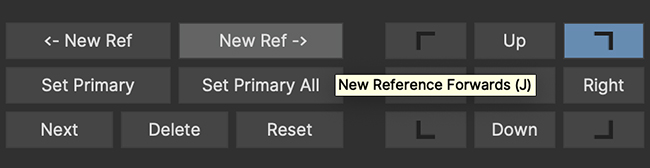
Because keyframing "thinks" forward, hitting "<-New Ref" will not create new Primary Reference points on the current frame, but will go backwards in time, looking for any existing keyframes and set new Primary Reference points on the frame directly after. For example, if you decide to create a new backwards reference point at frame 20, a new primary reference will be created at frame 21.
Some people may be more comfortable doing this manually by moving the playhead themselves and using the traditional "New Ref ->" button. Others who do a lot of tracking and find themselves working backwards often may find the backwards-thinking New Ref button helpful.
About Primary Reference Points (the red X)
Every Reference Point has one frame in which its initial placement is determined without causing any adjustment to the track. This is called the Primary Reference Point; if you step forward or backward in time you will notice the red X change to a red dot.
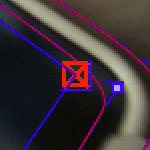
The red X indicates that this particular frame is the starting point for calculating adjustments. Moving a Primary Reference Point will NOT change the tracking data.
Go ahead and experiment - move the Reference Point when it is a red X (a Primary Reference Point). You will notice the Surface isn’t adjusted at all. Step forward a frame and move the same point - this time the surface will move because you are now adjusting the track.
Changing the Primary Frame for a Reference Point
By default, the frame in which you create a Reference Point is its Primary Reference frame. This Primary Reference can occur on a different frame for each reference point. You can change the Primary Reference frame by selecting a Reference Point, going to the appropriate frame and hitting the "Set Primary" button.
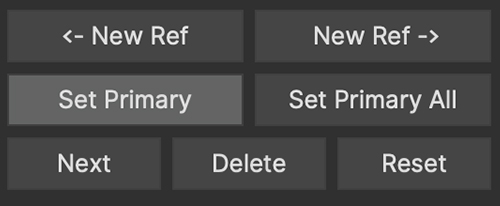
You may set a new Primary Reference Frame for all active points by hitting the Set Primary All button.
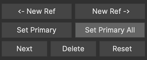
Selecting Different Reference Points
One method for selecting different reference points is to hit the "Next" button.
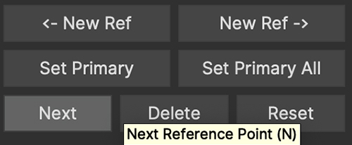
The next button simply cycles through the active reference points for that frame. More fine-grained control of reference points can be obtained through the Nudge control panel, described below.
Deleting Reference Points
Deleting Reference Points is done by selecting the point you wish to remove and hitting the delete key. If there are multiple Reference points on a particular corner, the preceding Reference Point will be extended through your time line until a new Reference point is encountered.
Nudging Reference Points
The Nudge section allows you to move Reference points in 0.1 pixel increments, much more fine grained than would be possible by dragging the points manually. You can easily select any active Reference Point by selecting one of the corner buttons in the Nudge section.
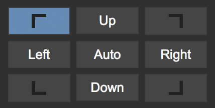
If you hit the Auto button, a tracker will attempt to line up the selected Reference Point based on its position in the Primary Reference frame. The Search Region Size and Maximum Motion parameters can be set in pixels in the Auto Nudge section.
You can quickly select any corner by using the Corner selector buttons in the Nudge control panel. In the image below, the user is selecting the upper right corner in preparation for nudging operations.
View Options
The Classic AdjustTrack tab has a View section for cleaning up your AdjustTrack workspace. Deselecting the Inactive Traces button will cause the display to hide the traces of the inactive Reference Points. This is helpful if you have a corner with numerous Reference Points offsetting it.
Deselecting the Unselected Traces button will hide any Reference Point that is not selected.
Finally, deselecting the Search Area button will hide the Search Region Size (in Yellow) and the Maximum Motion search area (in Pink).
Tips for AdjustTrack
Adjust frames at the peak of drift
When you see a drift, carefully cycle through the timeline and look for where the motion starts to change direction. A frame before this, adjust your drift, then go halfway between your primary frame and the adjusted frame to check for any further drift. If you keep working by checking halfway between each keyframe you set, you will reduce the amount of keyframes required.
A huge amount of keyframes is not a good sign
If you end up with adjustment keyframes on a large amount of frames it may be better retry the track. AdjustTrack is aimed to help reduce small anomalies and fix drift when a tracked corner has become obscured. If you are fixing every second keyframe it means you have more than a simple drift.
Rotoscoping Basics
| Some tools, parameters and techniques listed below may not be visible in Essentials mode. To see additional interface elements, switch to Classic mode. See the Layouts section for more information. |
The Art of Rotoscoping
Most often a good matte requires a combination of both keying and rotoscoping techniques.
Good rotoscoping artists often think like animators, reverse engineering the movements, the easing in and outs, the holds and overshoots of objects, and set their keyframes accordingly.
In general, the fewer the keyframes, the better your mattes will look. Too many keyframes will cause the edges to 'chatter' and move unnaturally. Too few keyframes will cause the shapes to drift and lose definition. Finding the right number and placement of keyframes often comes with experience but there are a few things to keep in mind when rotoscoping.
Traditional Roto Tips
There is no such thing as a perfect matte. Rotoscoping is an art form that takes into account the background image, the movement of the object, and the new elements to be composited in the background.
Try to start your shape at its most complex point in time, where it will need the most control points.
Break a complex shape into multiple simple shapes. If you are rotoscoping a humanoid form and an arm becomes visible, consider rotoscoping the arm as its own element, rather than adding extra points on the body that will serve no purpose when the arm is obscured.
Imagine you are the animator who created the shot. What would your dope sheet look like? No matter the medium, whether CG, live action or otherwise, most movements are rarely linear. They normally move in arcs; they normally accelerate in and out of stopped positions. Try and understand the mechanics behind how things are moving in your shot. This will help you to minimize keyframes.
Watch and study the shot before you start working. Where are the changes in directions? These will normally have keyframes. Where are the starts and stops? Are there camera moves that can be stabilized to make your work easier?
Don’t be afraid to trash your work and start over. Beginning roto artists often make the mistake of trying to fix a flawed approach by adding more and more keyframes. Experienced roto artists learn to quickly identify an inferior approach and are unashamed to trash their work and start over, often many, many times. It is very difficult to get a good matte without a conscious effort to keep the keyframes to a minimum.
Mocha Tracking and Roto
While you can refine a shape you have tracked to do your rotoscoping, the recommended way is to do a rough shape to track something and then link your roto to that track. This reduces the amount of work required when you are dealing with complex shapes, as you will not have to track and refine each shape as you go. It also means that if you have to retrack something you won’t have to redo a lot of layers. Another reason is reducing the amount of data needed in your project file.
It also helps to remember that your spline shape is linked to your tracking data and not the other way around.
For the following examples you can try out the tools using the BMW tutorial files
available from https://cdn.borisfx.com/borisfx/store/mocha-clips/rotoscoping.zip
Quick Shapes - Rectangle and Ellipse
You can use the Shape tools to quickly draw around objects in your view:
Rectangle: Select the tool and draw to size, or double-click to automatically create a Rectangle.
Ellipse: Select the tool and draw to size, or double-click to automatically create an Ellipse.
Holding the Shift key and double-clicking will make a uniform shape. In the case of Rectangles it will make a square, and for Ellipses a circle.
Rotoscoping Workflow
1. Track the area you want to rotoscope
First of all you want to reduce as much manual work as possible by tracking. In the example below, the front and side plane of the car is being tracked (For a more detailed coverage of tracking, see the Tracking Basics documentation).
![]()
2. Turn off your tracking shape
Once you’ve tracked an area it can be useful to turn it’s visibility off, as well as it’s tracking cog (so it can’t be accidentally retracked later). This means the tracked shape will not be confused with any roto shapes you are making.
3. Start drawing your refined shapes
Once you have a track for a layer we recommend that you add a new layer to use for the actual roto spline, rather than refining the spline you used for the actual track as you might need to do more tracking with it later.


Select the X spline or Bézier spline tool and draw a tight spline around the object you are rotoscoping. Ctrl/Cmd+drag the Bézier tangents if you wish to break them. You will see that a new layer is automatically created.
4. Link the new roto layer to your tracked layer
You don’t want to track with this layer, so disable tracking for the layer by turning off the tracking button (the cog) for the layer in the Layer Properties panel.
Rename the new layer and link it to the movement of your already tracked layer by selecting it from the 'Link to Track' dropdown in the layer properties panel.
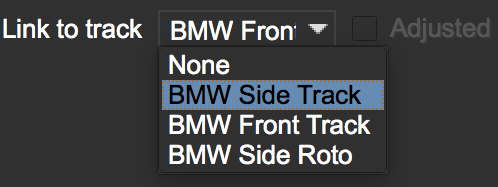
Your newly created roto spline will now follow the motion of the linked track.
5. Refine your roto
Now you have linked the rotoscoping layer to a track, you need to go over the timeline and make sure the roto is correctly animated.
Often you will need to tweak your shape for it to fit correctly, adding new keyframes. Autokey is on by default, so you just need to move along the timeline and adjust your points where necessary (keyframes turn up in the timeline as green dots). The tracking data will help for the majority of the motion.
You can also add additional shapes to the same layer using one of the "Add Spline to Layer" tools. These are the drawing icons with the plus sign next to them ("+").
You can cycle between each point on a spline with the keyboard shortcuts '{' and '}'. This is useful for when you need to do minor adjustments across many points separately.
6. Feather your edges if necessary
Edges can be feathered either by dragging out feathers point by point using the edge pointer tools in the toolbar or by using the parameters in the Edge Properties panel.
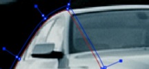
In the toolbar you have four different pointer tools:
The pointer tool with the 'B' will move both the inner and outer spline point (‘B' = ‘Both')
The 'I' pointer will only move the inner spline
The 'E' pointer will only move the outer spline point (‘E' = ‘Edge'). A feathered edge will occur between the inner and outer spline points
The 'A' pointer will remove either the inner or outer point depending on which is selected (‘A' = ‘Any')
You can also use the Edge Properties to feather the edge at the selected point(s) an exact amount or use the Add button to increase/decrease the feather by the specified amount.
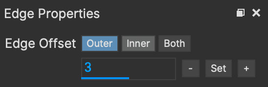
The Edge Offset buttons cover three different approaches to manipulating the edges:
Outer Edge (Default): Moves the outer edge feather in and out. You can also set this to a specific pixel width. This will not reduce below zero to avoid inverted feathering.
Inner Edge: Moves the inner edge up to the outer edge or towards the centre of the spline.
Both: Scales both the inner and out edge inward or outward. This is useful for tightening up a matte or expanding edges for garbage mattes.
For example, if you deselect all points by clicking anywhere on the canvas you can then use the Set button to apply the default 3 pixel edge width.
Because no points are selected the value is applied to all points on the current layer.
You can then tweak the position of all spline points to ensure that the inner (red) spline is inside the edge and the outer (blue) spline is outside the edge.
7. Track additional sections as you go
In many instances one track will not be enough. You may need to track more than one plane to drive different sets of roto. In the car example, we have to track the front and the side to get an accurate track for each planar region to assist the roto effectively.
In the case of organic shapes, like people, you will have to break your tracks down to handle the different movement between the torso and the arms etc.
Inserting Points
You can add more points to your shape either using the Point Insertion tool next to the main Pick/Selection tool, or hold down CMD/Ctrl while using the selection tool itself.
Removing Points
To remove points, simply select a point or series of points and press the delete key.
You can also hover over an existing point and hold down the CMD/Ctrl key to click-delete existing points in the spline.
What’s the Überkey?
The Überkey is a powerful tool that allows you to offset the positions of control points without destroying their keyframe data.

Use this tool with care, as it is not setting any keyframes per se, it is offsetting any and all keyframe data on the points you move while it is on. Überkey is very useful, but remember to turn it off again when you don’t need it. Use with care.
Überkey affects only those frames between the timeline’s In and Out point. If you wish to make adjustments to a particular range, set the In and Out points to that range.
Translate, Rotate and Scale your Splines
You can translate, rotate and scale selected points as a group by using the corresponding tools listed in the toolbar.


Or alternatively, use the transform tool to perform all of the above functions in the same tool:

Turning On and Off Points
You can turn on and off individual points in a spline. When they are off, you can still see the points, they can still be animated, but they are not contributing mathematically to the spline. This allows you to have a complex spline only when you need it, rather than having to deal with superfluous points in parts of the shot when they are not needed.

To turn off points, select the points on the spline and hit Shift+Delete. You will see the curve change shapes, but the points will remain.
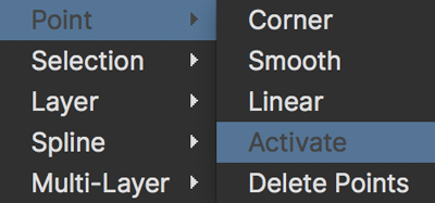
To turn a point back on, right-click on it and select Point | Activate.
If the Autokey button is enabled, a keyframe will be created when you change a point’s active status.
Add Motion Blur
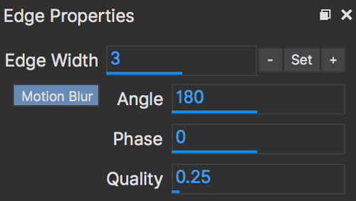
You can use the movement of the individual spline points to determine motion blur.
Any movement in the spline, whether through simple X/Y translation or by shape deformation will cause motion blur.
You can control the amount of blur by changing the motion blur value in the Edge Properties panel.
Angle
This essentially controls the amount of motion blur for the layer.
Angle simulates how long the shutter is open for if we were viewing through a real camera, so the range is between:
0 (closed, which means no motion blur)
360 (fully open and therefore the maximum motion blur possible).
The reason we refer to angle as opposed to "amount" is that camera shutters used to open with a rotary action, so a smaller angle would let in less light, and thus reduce motion blur.
Phase
This controls the offset of the motion blur from the current frame.
Changing Phase from zero shifts the position of the motion blur to either be more ahead or behind the currently calculated frame and is useful for tweaking motion blur that isn’t quite sitting right.
Because Phase is based on the shutter angle you can adjust between the range -180 and 180 (i.e a range of 360 like the shutter angle).
Quality
The steps of motion blur you want to render. The lower the quality, the faster the render speed. The default is 0.25 but can go as high as 5.0.
Previewing Motion Blur
If motion blur is enabled, you can preview an optimised version of it via the Show layer mattes button.
If you just want to view the mattes without the motion blur preview you can uncheck it from the button dropdown:

If you want to see the full quality rendered version, you can also select the clip preview dropdown in view controls and choose the Matte clip for that layer.

Changing the Matte Blend Mode
Although not necessary in this example, note that you can change how mattes are blended in the Layer Properties panel. You may make each layer’s matte Add or Subtract and you can also invert the matte.

Note that this can’t be keyframed and that these settings apply to the entire layer, not to individual splines of the same layer.
Viewing your Mattes
In the View Controls, several options are offered for viewing your mattes. The Matte drop down is has options to view all mattes, just the mattes you have selected or no mattes.
![]()
Select the Matte button and you will see your rotoscoped object against a flat background.
Changing the Background Color
You may wish to rotoscope against a particular color. Select View → Canvas Color… and a color picker will allow you to choose a particular background color

Colorize your Matte Overlay
When you have your Mattes turned on, you may choose for the matte to be filled with a color instead of cutting out the object, using Colorize.
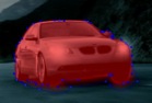
You can adjust the opacity of the color fill by changing the blend value to the right of the Colorize button.
![]()
The color used by Colorize is derived from the Selected and Unselected properties of the Overlay Colors panel, which can be changed per layer.
This is only a preview and will not affect how your mattes are rendered when exporting.
Hiding splines or points
If you want to get a better view of your roto, you can get a better view by turning off some overlays.
For layer spines:
Select your layer and turn on the Mattes button (Show Layer Mattes)
Uncheck the Splines option in the 'Show Spline Tangents' dropdown
For points:
Right-click the spline
Choose Layer > Hide points
Hiding points will still allow you to adjust the layer with the transform tool.
Preview Rendered Mattes
In the View Controls panel, you will find a drop-down menu for selecting the clip to view.

This allows you to view the actual rendered mattes, which can be especially useful when tweaking motion blur. The motion blur you normally see in your canvas is an OpenGL preview and can differ slightly from the actual render.
If you’d like to see what the actual motion blur render looks like, switch to viewing the layer whose matte you wish to see.
Because you can choose specific layers for export when you render, a render pass is created for each layer.

Switch the View Clip drop-down back to your source clip to continue working with that clip.
Open Splines
If you want to draw open splines, you can simply hold shift when you right-click to finish the spline. This will open the shape up.
You can open an existing shape using the Open Spline shortcut key (by default this is 'o')
You can close an existing shape using the Close Spline shortcut key (by default this is 'c')
Both the Open and Close shortcuts also work for finishing a spline rather than using Shift + Right-Click
You can also right-click a spline and choose: Spline | Open/Close Spline
Using Falloff for Adjusting Larger Clusters of Points
| This feature may only available in Mocha Pro |
Normally adjusting points is done by moving selections of points or carefully moving individual ones.
An alternative approach is to use the falloff tool to move contiguous points in a spline all at once with a gradient of strength.
With the selection tool active, you can click the falloff icon to activate the selection radius.
This is adjustable via a field in the Falloff panel:
Radius: Adjusts the size of the affected area
Strength Adjusts the strength of the falloff. At 100% all points within the radius are moved the same amount as the selected point.
You can use Ctrl/CMD and Left-Dragging to adjust the size of the Radius. Similarly, you can adjust the strength by holding Ctrl/CMD+Shift and Left-Dragging.
Adjustments are visualised by a red gradient, but this turns off while using the tool on points.

Any point on the line of control points near your selection that fall under the circle will be affected.
| The falloff tool doesn’t affect non-contiguous points, meaning nearby contours or loops will not be affected when adjusting. |
Splitting Contours into Different Layers
| This feature is only available in Mocha Pro |
Sometimes when you’re working on a complicated roto, you realise you really needed a few smaller shapes rather than one big one.
To remedy this, you can split any selected points into a new layer and they will retain the existing keyframes and tracking data.
To split a contour:
Select the points you want to split off
Go to the
Editmenu and selectSplit Contour
The shape should now be split at the point you selected.
A few caveats:
You can’t split off a shape using less than three points
Similarly, you can’t split off a shape if the original shape will be left with less than three points
You can’t split from more than one contour at a time. If you want to split multiple contours, just repeat the process for several selections.
| When splitting contours, PowerMesh tracking is retained across the entire area. This is to maintain any spline warping that may be lost if you deleted the mesh to just the spline boundaries. |
Snapshot Duplicates
| This feature may only available in Mocha Pro |
Some roto requires making copies of existing splines to continue a different part of the work.
To make this easier, you can use Snapshot Duplicate to make an exact in-place copy, which compiles both the keyframed position and tracked position into a new untracked layer.
This will also keep the surface in the exact same spot for that frame to make it easier to match corner pins or inserts.
To snapshot a layer:
Select the layer you want to duplicate
Go to the frame you want to snapshot
Under the
Editmenu, chooseSnapshot Layer at Current Frame
A new layer will be created that exactly matches the position of the original layer without any of the animation or tracking keys.
You can of course just copy splines or duplicate layers normally, but with these methods you’re often left with more work to do to remove keyframes or readjust splines into position.
Displaying spline contours for a single frame
Sometimes you may only need a contour in your layer for a single frame.
This very useful for example in Matte Assist ML, but it also has other uses for dealing with single-frame roto problems.
To turn on single-frame splines for a contour:
Go to the frame the contour was drawn on
Right-click the spline
Choose
SplinethenSingle frame On
This will reactivate the spline contour for the rest of the frames in the timeline.
To switch it back off, simply repeat the same process, but this time select Single frame Off.
Compositing a Group of Layers
You can combine the mattes of individual layers into a single matte by grouping them.
This is done using Composite Layers in Group in the Matte Module.

Add layers into a group folder in the Layer controls
Name the group something useful!
With the group selected, check the
Composite Layers in Groupcheckbox in the Matte module
Combined group mattes appear in the matte clip list with a 'group' prefix. These matte clips can be rendered to disk using Export Rendered Shapes or rendering to the host.
If you have Composite Layers in Group assigned, it will override any individual mattes in the group when rendering from the plugin. |
Composite group mattes can be used anywhere you use mattes inside Mocha.
For example, you can use a group matte for holding out clips in the Insert module or use them to assist occlusions in the Remove module.
Tips for Rotoscoping
Name your layers
Naming layers is very important to save yourself time later, especially if you are doing a heavy rotoscoping job. Get into the habit of labeling each layer with specific names.
Turn off the splines and just work with points and the matte
If you are working on a tight roto it can sometimes be easier to turn the spline off and just see the matte with the control points. To do this:
Select your layer and turn on the Mattes button (Show Layer Mattes)
Uncheck the Splines option in the 'Show Spline Tangents' dropdown
If your other view options are at default settings you should now see the matte in the viewer with only the tangents and control points visible.
Rotoscoping with Magnetic and Freehand Tools
The magnetic and freehand tools provide an easy way to quickly roto an object.
The Magnetic Tool

The Magnetic Tool draws a pixel line that snaps to the nearest edge to where the cursor lies, tracing the shortest path from any previous click.
To use the Magnetic Tool:
Select the tool from the toolbar.
Click once near the edge you want to start with
Move your cursor along the edge you want to follow
Click once any time you want to anchor the currently drawn path along the route
If there is a tricky section of the edge that the magnetic tool doesn’t want to line up to,
you can press and hold the mouse/pen down and the tool will switch to Freehand mode.
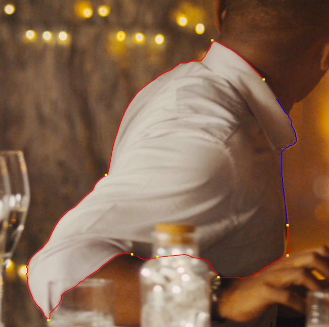
(Image courtesy of LateNite Films)
Similarly, if you go off the edge of the frame, the magnetic tool will also switch to Freehand mode,
so you can freely continue the shape.
The Freehand Tool

The Freehand pen tool is exactly like the Magnetic tool, minus the magnetic properties.
This gives you the freedom to quickly draw any line.
You can access the Freehand tool in the same tool drop down as the Magnetic tool, but also any time you
press and hold the mouse/pen down in the Magnetic tool, or go off the image frame.
Finalising a Drawn Line
One you have completed a drawn line, you can either click back on the original point, or right-click.
This will generate an X-Spline that follows the originally drawn line.
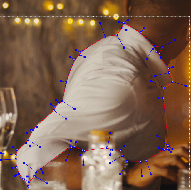
(Image courtesy of LateNite Films)
Adjusting Detail
X-Splines generated by the Magnetic and Freehand tools have a fairly high point count to match the subtle changes in the line.
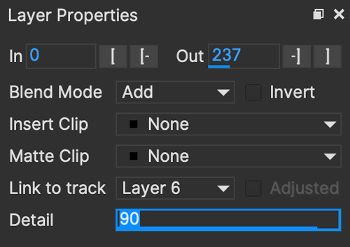
If you want to increase or reduce this detail:
Finish drawing the line and right-click. This will automatically switch your cursor to the selection tool.
With the completed layer selected, choose the Magnetic or Freehand tool again.
The Detail parameter will enable in the Layer Properties panel
Adjust detail to increase or reduce the number of spline points
| Adjusting the detail of a magnetic or freehand line will move the points back to their original positions to re-fit the line. |
| Animation or extended editing of a magnetic or freehand layer spline may permanently convert it to a regular spline. |
Edge Snapping
You can snap the control points of any spline to edges of an object by using the Edge Snapping tool.
By default, this is the 'Alt+S' keys.
To snap to an edge:
Select the points you want to move
Press the 'Alt+S' key once to snap
Alternatively hold the 'S' key and drag the points.
The selected points should then move to snap to the nearest detectable edge.
Keep in mind this will naturally try to find the most visible edge, so in some cases snap may not find the edge you want.
In these cases it may need to be adjusted manually.
Painting Splines with the Area Brush Tool
The Area Brush produces X-Splines based on paint strokes in the viewer canvas.
You can also paint on an existing layer with the "Add" paint brush.
Paint strokes that cross over an existing layer spline will intersect with that spline, or subtract from it if you are using the alt modifier key.
| Area Brush is currently a single-frame paint effect. It is not keyframeable. |
Painting new layers with Area Brush
You can select the Area brush from the toolbar:

![]()
Selecting the area brush reveals the Area brush settings further down the toolbar:
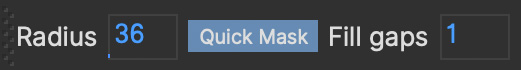
You can now paint on the canvas and a red paint area will appear.
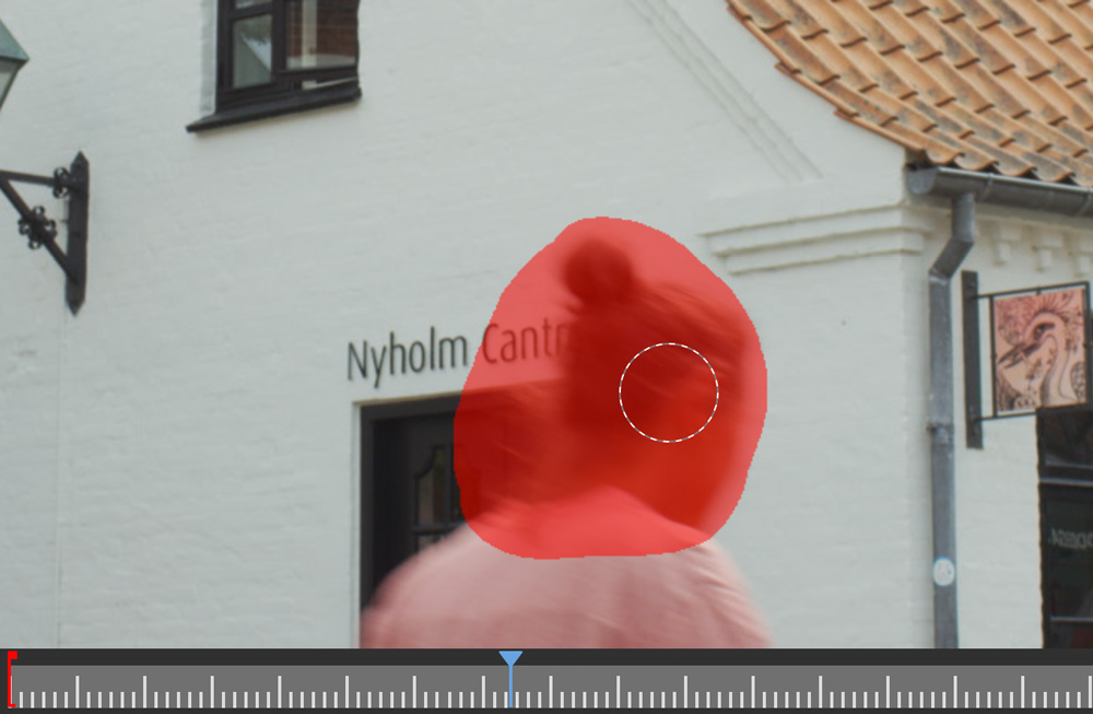
Once done, you can turn off Quick Mask if it is on or just release the mouse button and a spline will be generated.

Adjusting the size of the brush
You can adjust the brush size using either:
The radius keys (by default this is '[' and ']').
Holding down the CMD/Ctrl key and dragging the cursor
Editing the radius field directly in the Area Brush toolbar
For finer control, the brush size will also change according to the set pressure sensitivity from a drawing tablet.
You can turn off pressure sensitivity from Preferences.
Quick Mask
By default, Quick Mask is turned on.
Quick Mask stops the Area Brush tool from generating a spline as soon as you release the mouse or lift the tablet pen
Once you have painted what you need, you can turn Quick Mask off by pressing the button and the spline will be generated.
Fill Gaps
If you want to quickly fill smaller gaps, you can adjust the "Fill Gaps" field.
The number in the field is a pixel diameter. Any gap in a closed painted area that is smaller than the number in the field will be filled.
For example:
A Fill Gap diameter of 1 will only fill tiny gaps.
A Fill Gap diameter of 1000 in a 1920x1080 image will close very large gaps.
A large fill gap setting is useful for quickly circling an object with paint to make a filled spline.
Add Area Brush to Layer
The Add Area Brush will add new paint-generated splines to the selected layer.
![]()
The tool is under the main Area Brush icon. Just press and hold the toolbar icon to select the brush from the list:
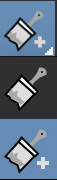
Then you can paint on the existing spline:
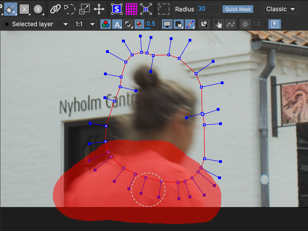
Once done, you can turn off Quick Mask if it is on or just release the mouse button and the resulting spline intersect with the existing layer splines:
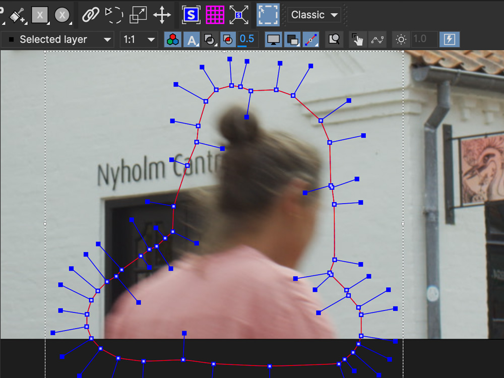
Erase
In both Quick Mask mode and normal painting mode, you can hold down the alt/option key to switch to erase mode.
In Quick Mask mode, this will erase existing paint:
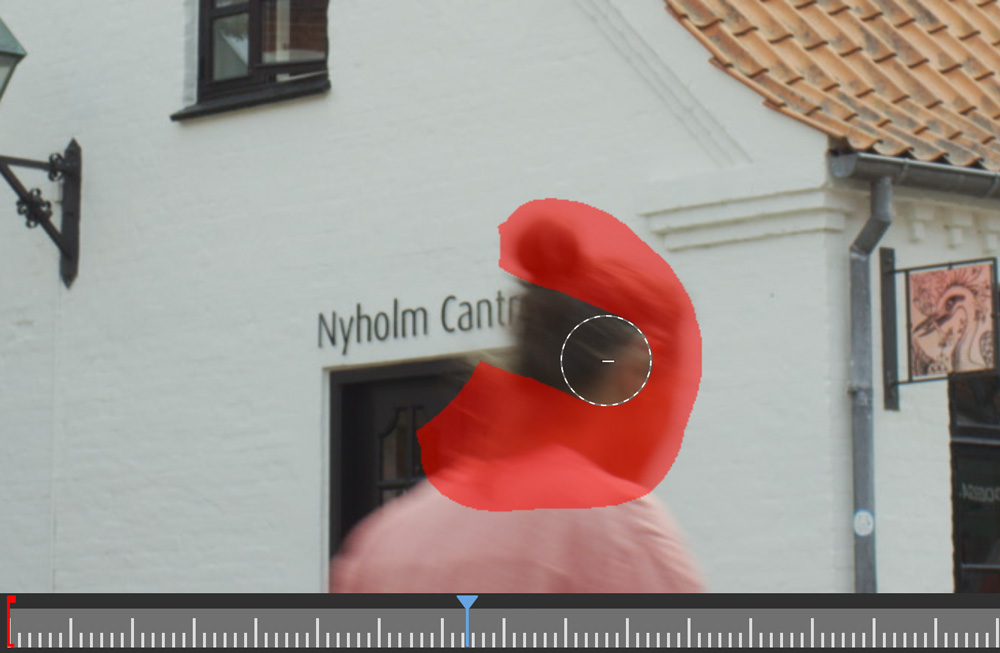
If Quick Mask mode is off, this will erase the existing spline if you are using the Add Area Brush tool. Just paint as normal holding down the modifier key:

When you release, the erase will eat into the existing spline:

Creating Mattes with Machine Learning Tools
You can get assistance with building mattes and rotoscoping by using the machine learning tools in Mocha.
| The Machine Learning tools are designed to assist with your general workflow, especially for streamlining garbage mattes. They are not designed to replace fine-detailed rotoscoping! |
The Object Brush
The Object Brush is used to select objects in the shot using the Boris FX Mask ML process.
The resulting matte is similar to the Area Brush in that it creates a painted matte area which is then converted into a spline.
Selected objects that cross over an existing layer spline will intersect with that spline.
Selecting objects with the Object Brush
You can select the Object brush from the toolbar:


Selecting the Object brush reveals the Object brush settings further down the toolbar:

Preview
Hovering over any part of the frame will provide an automatic preview of the area that will be selected. You can turn Preview off in the toolbar.
| When using the Object Brush for the first time, there will be a slight pause as the tool is loaded into memory. After that Preview will be very fast. |
By default, preview will show a lower resolution version of the mask to keep the overlay display fast.
If you would prefer a different resolution, you can click on the dropdown to the right of the Preview button and change the resolution between 1:1 to 1:4,
or leave it on Auto to change the resolution based on the speed of the mask update.
| You can set whether Object Brush Preview is on or off by default in Preferences. |
Selecting objects
You can now select the area on the canvas you want to be covered by left-clicking on it:
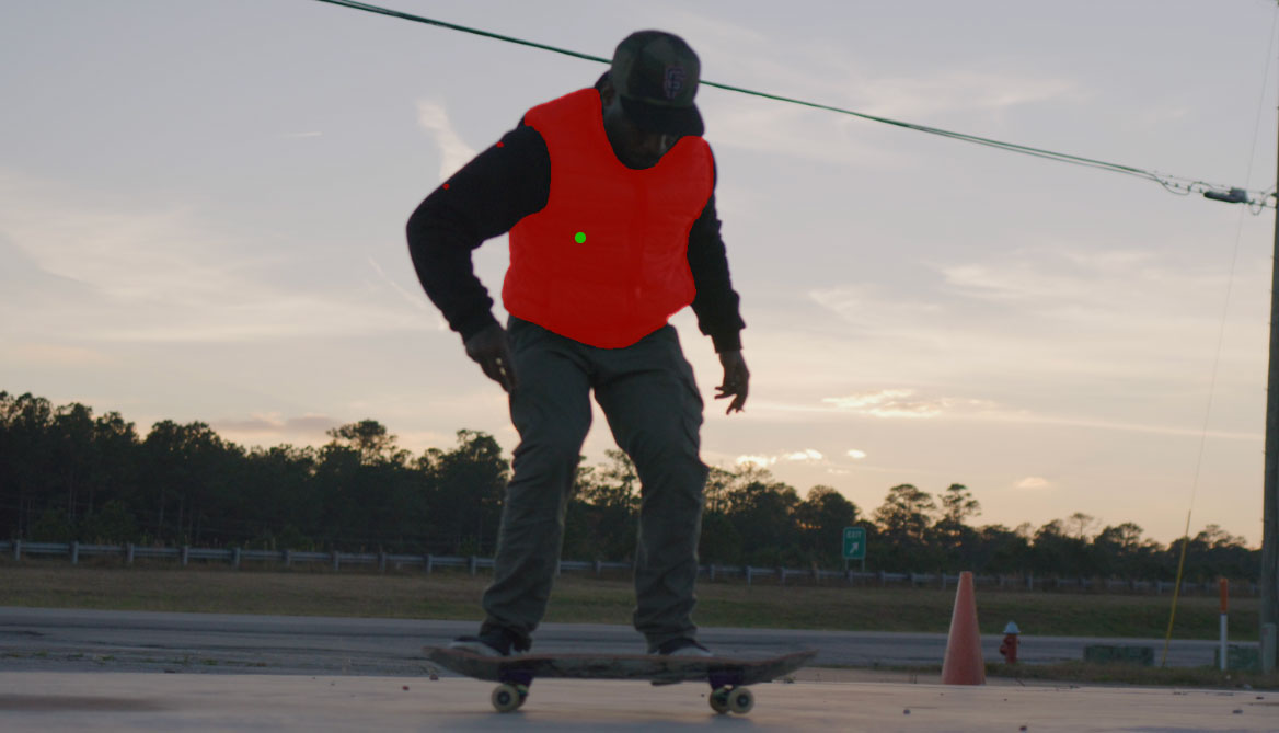
You can select more areas by left-clicking again. Note the green dots that appear as you do this:

If there is an area you don’t want to be covered, you can right-click and a red dot will appear in that area:
Once done, you can select the pick tool again:
Or click the Finish button in the toolbar options on the toolbar:
This will finalize the matte and a spline contour will be created on that frame: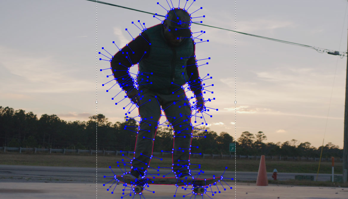
Auto ROI
When clicking with the object brush, you will notice a dashed box around the area you click.

This is the automatic region of interest (ROI) that the Object Brush will be looking inside for the edges of your object.
The Auto ROI helps narrow the focus of the tool so you can get better detail in your final spline.
Auto ROI is on by default is is fairly accurate at containing the area to be defined.
You can modify the size of the boundary for the ROI by changing the value to the right of the Auto ROI button.
If you want to specify your own Region of Interest, you can click the Auto ROI button to turn it off and use CMD/Ctrl+ Left Mouse Button to drag out your own area.
| If a Region of Interest is not defined, Mocha will look at the entire image to make the mask, which can result in lower quality results. |
Creating more frames with the Object Brush
The big difference between the Object Brush and other drawing tools is that selecting an object will only create a contour for the frame you are currently on.
You will not see the spline on other frames.
The benefit of this is that you can select the same object on other frames to create additional contours.
This is very helpful for creating reference frames for Matte Assist ML, which is covered in the next section.
To add a new contour to the same layer on another frame in the timeline:
Move to the frame in the timeline where you want to select the same object again
Select the "Add Mask ML to layer" Object brush in the brush dropdown:

Follow the same steps for selecting objects with the Object Brush above.
When you create the new spline, it will generate a keyframe on the timeline for that frame. Now you will have 2 contours in the layer but they will only be visible on the frames you created them on.
You can repeat this process for as many frames as you need.
Turning off and on the single frame contours for Object Brush
While it is very helpful for Matte Assist ML to have single-frame contours, you may also want to use the Object Brush spline for more frames.
To turn off single-frame splines for a contour:
Go to the frame the contour was drawn on
Right-click the spline
Choose
SplinethenSingle frame Off

This will reactivate the spline contour for the rest of the frames in the timeline.
To switch it back on, simply repeat the same process, but this time select Single frame On.
Fill Gaps
If you want to quickly fill smaller gaps, you can adjust the "Fill Gaps" field.
The number in the field is a pixel diameter. Any gap in a closed painted Object that is smaller than the number in the field will be filled.
For example:
A Fill Gap diameter of 1 will only fill tiny gaps.
A Fill Gap diameter of 1000 in a 1920x1080 image will close very large gaps.
A large fill gap setting is useful for quickly circling an object with paint to make a filled spline.
Editing the Object Brush Matte
If the result from Object Brush is not quite looking correct, you can switch to the Area Brush tool to add or erase matte areas before you turn it into a spline.
To do this:
Select your object by following the Object Brush instructions above, but don’t choose the Pick tool to finish yet.
Switch to the Area Brush tool
Paint or erase the parts that need to be corrected
Select the Pick tool to finish.
Because the painted matte shares the same properties across Area Brush and the Object Brush, you can switch between them as you like.
Just make sure you use the "Add" version of the tool if you are adding another contour!
Editing the Object Brush Spline
Once you have completed the matte and it converts to a layer spline, you can edit it like any other spline, refining the shape further if necessary.
Matte Assist ML
You can automate the generation of animated garbage mattes using Matte Assist ML.
To start using Matte Assist ML, first switch to the Matte module:

Reference frames
In order to use Matte Assist ML, you will need to draw a layer so the generator has something to reference.
We recommend using the Object Brush as this is designed specifically to work in conjunction with Matte Assist ML, but you can also hand-draw your own layer using the regular spline tools.
As a general rule, try to keep the edge of the layer spline as close to the edge of the object as possible, or even inside it.
One reference frame may be enough, but if you notice problems in the matte after generation, we recommend creating addtional keyframes.
With the Object Brush this is handled by creating individual contours on separate frames, but you can achieve the same thing with a regular layer spline by simply adjusting the spline to match the object on a different frame.
| Matte Assist ML will ignore any animation between keyframes. It only looks at the specific keyframes, not the motion in the spline. |
Rendering the Matte
Once you have a reference spline and one or more keyframes, you can then render the matte.
In the Matte Module, select the layer you want to use and make sure the processing cog is turned on
Turn on "Generate Object Matte". By default this is toggled on if you use the Object Brush to generate your reference spline. The selected layer will now have an icon to flag that it is using the Matte Assist ML clip:
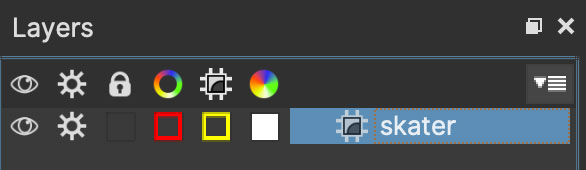
Press Render Forwards in the timeline controls
Mocha will then take the reference keyframes and generate an animated garbage matte for the whole timeline. This will keep the existing contours, but every other frame will be an uneditable Vector Matte Clip (see below).
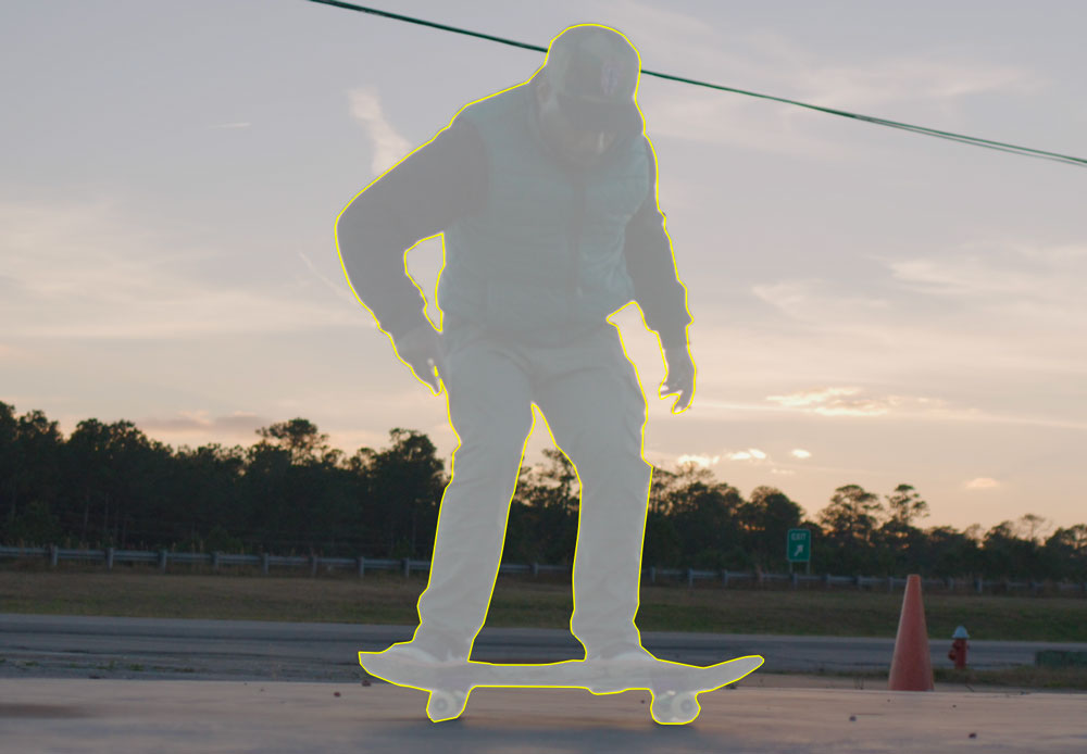
You can change the colour of the matte in the layer controls like any other spline, and you can also change the vector matte clip outline by changing the colour of the column with the Matte Assist "Chip" icon:
Search Area
You can get a tighter matte by defining a search area.
Similar to Object Brush Auto ROI, this looks in a boundary around the current matte to get more detail.
This option is off by default. To turn it on, click the checkbox next to Apply Search Area:
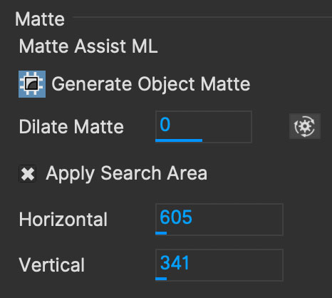
The Horizontal and Vertical fields will automatically be filled with pixel values based on the size of the frame and you can modify these values as needed.
Vector Matte Clips
The matte clip generated by Matte Assist ML is different to regular image-based matte clips. It is instead using a vector-based matte that is saved to the project file.
This makes the matte very lightweight and can stay with the project, rather than having to rendered to disk.
| Due to the fine detail of the vector mattes you cannot view the underlying points on the matte clip as it would be cumbersome and impractical. |
Editing the Matte
If Matte Assist ML doesn’t quite generate what you need, you can modify the reference frame spline or add more frames to help generate a better result.
When you make any modification to the layer, the edge of the matte becomes dashed to indicate something has changed and you might want to re-render.
The matte itself will still render regardless of whether it is in this dashed state or not:

| If you cut off any reference frames by setting in/out points in the Project range or a layer range, those reference keyframes will not be available if you re-render the result. |
If a Matte Assist ML frame has problems that cannot be fixed by generating new reference frames, you can convert that frame to a regular spline by using the Reference from Matte button:
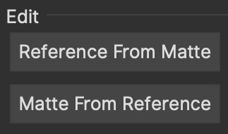
You can then modify this spline frame, delete or add new points and then convert it back to the Matte by clicking the Matte from Reference button.
For example, in this shot, there is a stubborn hole appearing on the sleeve of this arm:
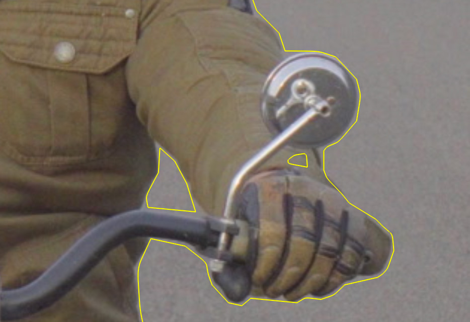
If we click Reference from Matte on this frame, it converts the matte to a spline:
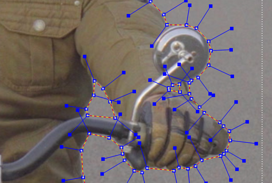
We can then delete the offending points:
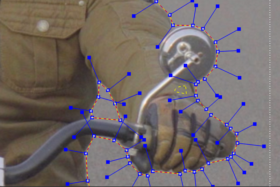
And finally, click Matte from Reference to convert the spline back to a MAML matte:
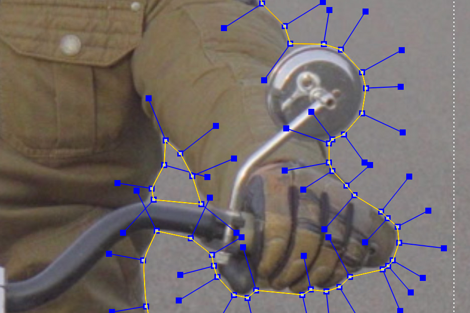
Dilate Matte
You can also dilate the matte to constrict or expand the edge, depending on your needs.
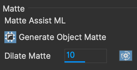
Dilation happens at render time, so you need to re-render if you change the dilation setting.
Because of this, Dilate Matte also include a toggle button to automatically re-render the current frame you are on if you change the Dilate value, to make it quicker to see your changes.

You will still need to re-render the whole timeline however if you make a change.
Matte Refine

By default, mattes have hard edges unless you feather them. While regular X-Splines and Bezier spline layers can be manually feathered using the Edge Properties, generated matte clips like Matte Assist ML need to be treated by a secondary Refine step.
| Matte Refine is automatically generated on the existing mattes during playback. There is no need to use the render buttons to generate Refined mattes. |
To refine a layer matte:
Turn on
Refine Layer Mattein the Refine section of the matte moduleChoose the refinement type:
Softer Edges: This version helps with heavily blurred and fast moving objects
Sharper Edges: This is a cleaner edge that is good for softening for fur, hairs, and sharper mattes that still need some softness.
Adjust the Refine parameters to clean up any problem edges
Refine parameters
Refine can be adjusted with the following options:
Black Clip: Make matte edges more transparent. This is useful for reducing the edge of the refinement where gray areas might be bleeding too much into the background.
White Clip: Make matte edges more opaque. This is useful for filling the inside of the refinement where gray areas might be creating holes.
Edge Grow: Add more detail to sharper edges
Shrink/Grow: Choke or expand the refined matte
Blur: Blur the refined edge further
Edge Only: Check this on if you only want to see the refined edge and not the filled-in matte.
Auto ROI:* Define how many pixels outside the object to create refined edges. This helps to clean up any potential artefacts.
Reset: Clear all settings back to the default.
Refining a Group of Layers
Using Composite Layers in Group in the Matte Module, you can refine a whole group of layer mattes in one pass.
Add any layers you want to refine into a single group folder in the Layer controls
Name the group something useful!
With the group selected, check the
Composite Layers in Groupcheckbox in the Matte moduleTurn on Refine for the group
This will then allow you to refine the entire composited group matte instead of applying to individual layers.
Stereo Rotoscoping
Stereo Roto works in a very similar fashion to stereo tracking.
Select the hero view (by default this is Left)
Draw a new basic shape and track the object you want to rotoscope as outlined above in "Stereo Tracking"
Draw a new refined roto layer around your tracked object
Click the "Link to track" drop down in Layer Properties and choose the previously tracked layer
Continue to refine the Hero view roto until you are happy with that view
Switch to the non-Hero view and begin refining this view.
When you switch to the non-Hero view the rotoscoping will be offset by the tracking data. While this will not completely refine the result, it will save you a lot of time.
Whenever you manipulate a control point in the Hero view it will offset that control point in the non-Hero view.
When you start to tweak the non-Hero view it will also generate new keyframes for that view only and will not affect the Hero view. You can see these keyframes represented in the timeline by split left and right keys.

If you wish to directly modify the control point in both views when working in either view, you can turn on the "Apply Keyframe Changes to All Views" button at the very end of the timeline controls to the right.
| If you insert additional points to a shape while in the non-Hero view, they will be automatically deactivated in the Hero view to avoid destroying the work done in the Hero view. You can reactivate these points in the Hero view by right clicking them and choosing "Point > Activate" |
Working with Difference Mode and Stereo Offsets
If you need to offset your tracking or roto manually (see below), you can use the Difference 3D view to help align the layer.
Select the layer you want to align
Turn on Difference mode.
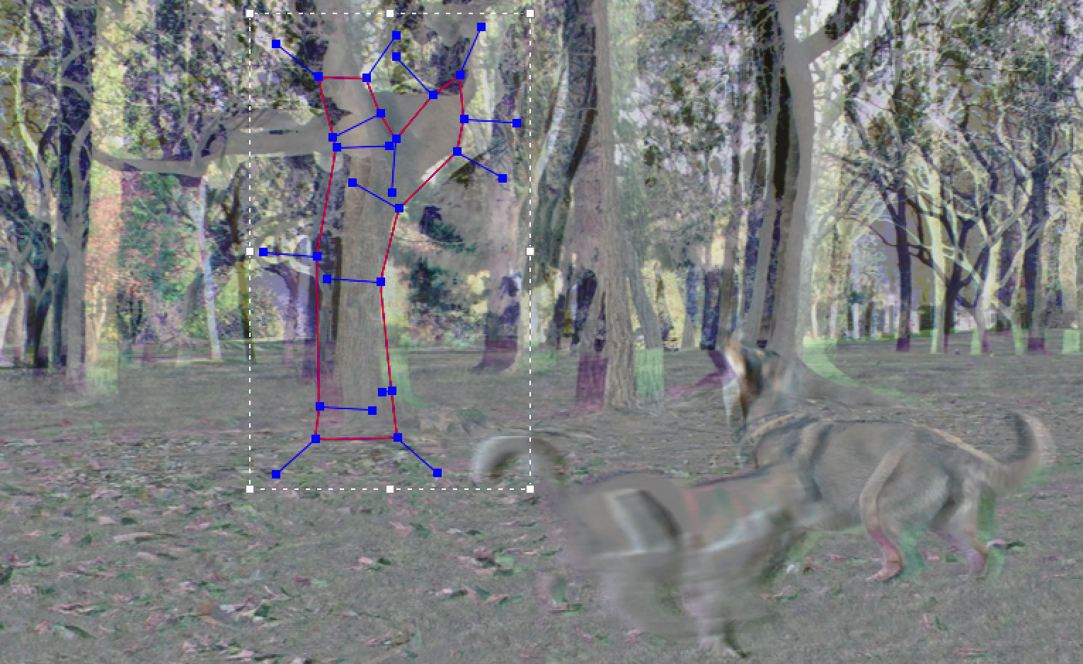
Go to the Stereo tab in the Track module
Select your Non-Hero View.
Offset X and Y until the screen gets as close to blank middle Gray as possible. You can optionally also adjust the other Stereo parameters.
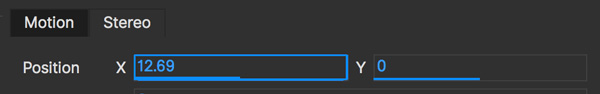
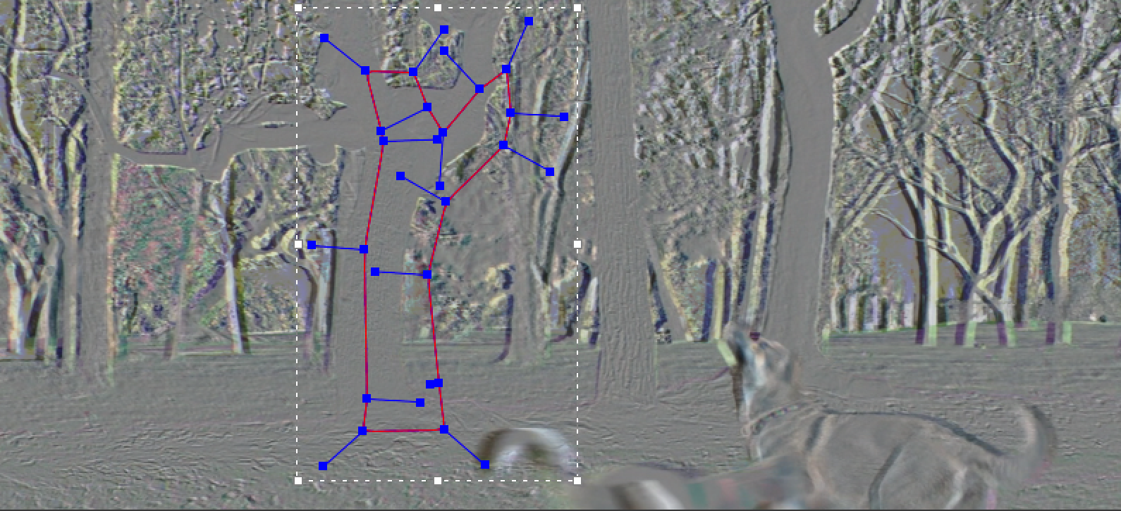
Turn off Difference view and review your results on your Non-Hero view.
The Export Data Dialog
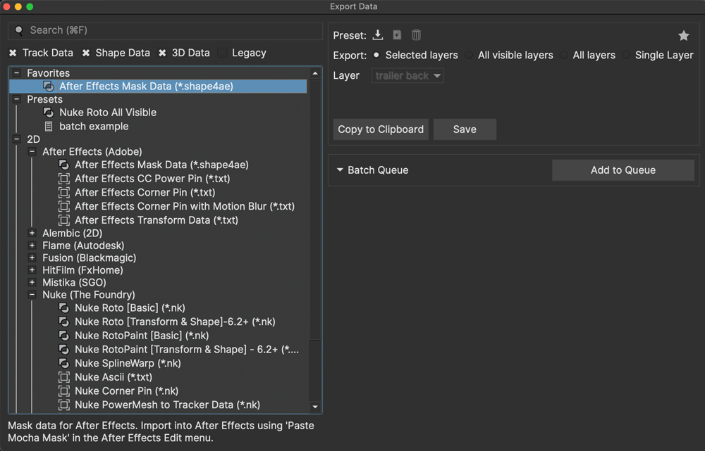
When you choose to export anywhere in Mocha, you will be presented with the Export Data dialog.
The Export Data dialog is broken into categories in the lefthand panel based on supported hosts and also formats that are not tied to any specific host.
The panel on the right of the Export Data dialog is where the export options of the selected data type will appear.
If you export from the File menu, you will get all data types, but if you are only interested in Tracking Data you can filter that down with the data checkboxes, or click the Export Tracking Data button in the Track module to auto-filter to tracking.
Selecting your chosen format, you can then usually either Copy to Clipboard (if the supported host allows clipboard data) or save the file to disk.
| The Export Dialog will stay on top of the main interface but you can keep it open while working. This means you can update your selections, visibility etc. before you export without having to close the dialog. |
2D Data Formats
Data in the 2D category covers tracking data, Shape (Roto) data and some special types such as 2D alembic data.
For more information on exporting Tracking data, go to the Exporting Tracks section of the User Guide.
For more information on exporting Mattes or Rotoscoping data, go to the Exporting Mattes and Clips section of the User Guide.
3D Data Formats
All data in the 3D category covers export formats for the 3D Camera Solver.
For more information on exporting 3D data, go to the Exporting Camera Solves section of the User Guide.
Legacy Formats
Mocha Pro supports many different VFX applications, including ones that are less used or have become obsolete.
This means over time, a lot more formats are shown in the exports than most users need.
By default we now filter out those formats in the Legacy category.
If you are still using some of these formats, just turn the checkbox on.
Favorites
You can tag any export type as one of your favorites so it appears at the top of the export format tree.

To favorite an export format:
Select the format you want to favorite
Click the star icon in the top right corner of the export format options

To remove an export format from the favorite list:
Select the format you want to remove
Click the star icon in the top right corner of the export format options to deselect it
Presets
You can define presets for options in the export data that you use frequently.
For example, you may always choose "All Visible Layers" for a shape export, or you may always want to turn off feature points in FBX data.
To save a preset:
Select the data export you want to use (Track, Shape or 3D Data)
Select the options you want for that export type
Click the
Save Presetbutton in the top left corner of the options:
You will be presented with a small naming dialog. Name your preset what you like and click OK
The preset will then appear at the top of the export tree, just under the Favourites.
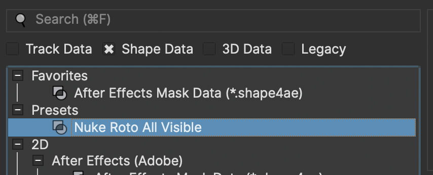
Renaming a Preset
You can double-click a preset in the export tree to rename it.
Duplicating a Preset
You can copy a preset by selecting the preset in the export tree and clicking the duplicate icon in the top left corner of the options.
A new preset will appear in the tree with an incremented number.
Deleting a Preset
To delete a preset simply select the preset in the export tree and click the trash can icon in the top left corner of the options.
The Preset File
Presets are saved in JSON format in the local preset directory, in the same path as the keyboard shortcuts and the default Python scripts directory.
Those familiar with JSON can easily edit this file if they want to set up presets as part of a studio pipeline.
By default the presets are saved in the following location:
macOS:
~/Library/Application Support/BorisFX/Mocha Pro/Windows:
C:\Users\[username]\AppData\Roaming\BorisFX\Mocha Pro\Linux:
~/.config/BorisFX/Mocha Pro/
Batching Exports
The batch queue allows you to set up a series of exports and save them to disk. You can also save this queue as a preset to be used across multiple projects.

The Batch Queue is helpful if you have a few different exports to make, or you have a series of projects that will require the same set of exports.
The queue can take an export of any type, including presets.
To add exports to the Batch Queue:
Select your data type and modify the options as needed
Click
Add to Queuein the Batch section on the rightEdit the default path and name of the export if needed
Repeat for other exports
Click
Batch Exportsto export the whole queueClick
Clear Queueto clear all items from the queue.
Editing the Batch Queue
If you need to change the options of an export in the queue, simply click it and make any adjustments.
You will see the Options go into "Editing" mode and the Add to Queue button will change to Update Queue Item:
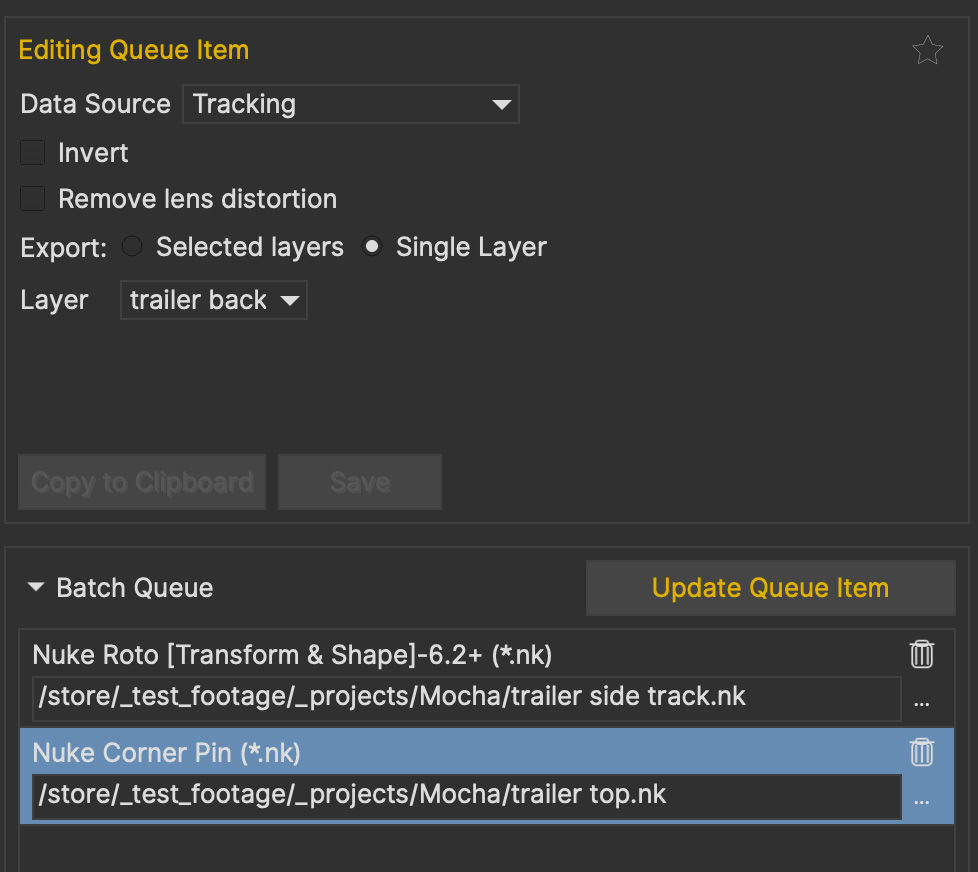
When you have finished editing, click the Update Queue Item button to update the queue.
Replacing or adding Multiple Batches
If you have an existing Batch Queue and select a saved Batch from the Presets, you will be presented with a dialog.
You can choose to cancel, append the saved batch to the queue, or replace the queue entirely with the saved batch.
Saving the Batch Queue
You can also save the queue by clicking the Save Queue button and naming your batch. This will appear in the Preset section with a Batch icon.
The saved batch preset is in the same JSON format as the presets, making it easy to edit externally. See The Preset File above for more details.
Export Again
If you are mostly using one format type in your Mocha work, we also offer the option to simply export that type again.
You can choose the Export Again option from the file menu or use the default shortcut CMD/Ctrl + R.
If you chose to save to disk previously, a save dialog will immediately appear when you select Export Again.
If you chose to copy to the clipboard, you will be notified that the data was copied to the clipboard in the progress bar.
Exporting Tracks
| Some sections only relate to Mocha Pro. Some export features are not available in Mocha HitFilm or Mocha AE. For a full comparison of features, please refer to the comparison chart online. |
| Tracking data is not supported across 360 seams and poles when using VR features and may not export as expected. |
Exporting data is the most useful way to get your tracks out to other applications.
In all cases below, you can export either from:
The Essentials Panel:

The Export buttons in the Track and AdjustTrack Modules:

Or the file menu:

Exporting Tracks to Adobe After Effects
| It is important that the clip length, frame rate, frame size, interlace mode, pulldown mode and pixel aspect ratio in the project match the corresponding settings in the After Effects project where you plan to use the data. You can change the frame rate and pixel aspect ratio settings in the Film and Time sections of the Clip tab. |
To export tracking data to After Effects, press the Export Tracking Data button.
Then from the After Effects (Adobe) section of the export dialog choose either:
After Effects CC Power Pin
After Effects Corner Pin
After Effects Corner Pin with Motion Blur
After Effects Transform Data.
After Effects CC Power Pin:
The Power pin data is very much like corner pin, but the exported effect gives you more control over the results in After Effects.
See the After Effects help for more information on how to use CC Power Pin.
After Effects Corner Pin:
The corner pin data records and exports the 4 point x, y information from either the adjusted track or the raw track.
There are three different types of corner pin exports – two for recent After Effects versions and one for CS3 and older versions of After Effects.
Some will be hidden in the Legacy section of the export dialog which you can reveal by turning on the Legacy checkbox.
After Effects Transform Data:
The transform data exports x and x positions as well as the scale and rotation for the whole surface.
If you click Save, this will display a file browser for saving the tracking data for use later. By default, the files will take the name of the layer, so for a layer name Track_Layer the export will create a file named "Track_Layer.txt".
If you don’t need to save the export, you can press Copy to Clipboard, and then go straight to After Effects and paste the data. If you are saving to file you will need to open the text file you saved with the data, select the entire body of text and copy it.
In After Effects, load the footage you tracked and the footage/image/composition you wish to apply the transform or corner pin data to.
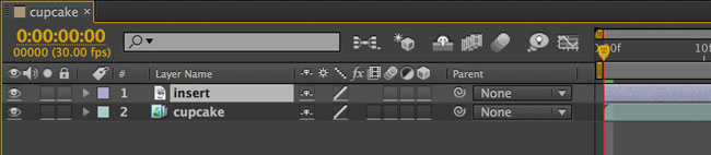
Select the item on the timeline that is the insert object. Paste the data to the selected layer. You can do this by selecting the ‘paste' option in the edit menu or by typing 'command- v' (Mac) or 'ctrl-v' (Windows).

With the layer’s information expanded you can see either the 4-point tracking data for the corner pin, or the position, rotation and scale information from the tracking is now applied to the insert layer.
If you are pasting transform data rather than corner pin data then you will need to delete the anchor point keyframes to see a result. We export both position and anchor point keyframes so that stabilization or tracking can be achieved. See below.
Applying Corner Pin for Layers with different dimensions
If your insert is not the same size as the dimensions of the composition in After Effects, you will need to take a few further steps to make sure your corner pin data fits correctly. The reason for this is that tracking data is basing itself on the relative size and aspect ratio of the footage, whereas After Effects treats the corner pin data relative to the size of the layer you are applying it to.
To get around this, you can take the following steps to modify the insert layer in After Effects:
Precompose the layer and move all attributes into the new composition.

Open the Precomp you just made and fit the layer to the composition dimensions (Layer | Transform | Fit to Comp).

Go back to the original composition, select the precomposed layer and paste the data.
Alternatively you can use Align Surface in Mocha to define the full dimensions:
Apply a manual corner pin to your insert layer in After Effects and place it in the desired position for any frame.
On this frame, Precompose the layer and make sure all attributes are inside it.
You will now have a precomposed layer that is the same dimensions as the tracked footage.
In Mocha, go to the same frame in the footage you applied the corner pin to in After Effects and select the track.
On this frame, turn on your surface and click "Align Surface" in the Layer Properties panel.
You will see the surface fit to the full dimensions of the footage.
Export this newly aligned track to After Effects corner pin.
Back in After Effects, select the precomposed layer and paste the data.
This will apply the tracking data relative to the full dimensions of the footage instead. If you need to adjust the insert, just open the precomposed layer and tweak the manual corner pin you made.
Using Tracks For Stabilizing In After Effects
You can use the tracking data created to stabilize a shot in After Effects.
Track your footage as normal, then turn on the Surface button and center the surface box on the area you wish to use as the stabilize center.
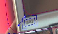
Export the tracking data in the After Effects Transform format. Select the Invert checkbox option
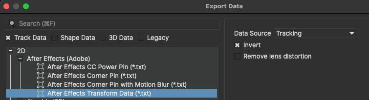
Switch to After Effects, select the layer you wish to apply the stabilize data to and paste it to that layer.
You should now have a stabilized image.
Alternatively you can also use the After Effect Corner Pin export using Invert in the same way to get a correctly warped stabilized image.
Exporting Tracks to Silhouette
This section explains how to export tracking data in a format readable to Silhouette Tracker nodes, how to import the data into Silhouette and how to use it for match move tasks.
| External clipboard data support from Mocha is only available in Silhouette 2020.0.1 and above |
Track an object in the usual way, and use AdjustTrack to correct for any drift if necessary. The exported tracking points will be the four corner points of the Surface, so you should position these appropriately.
Press the Export Tracking Data button on either the Track or AdjustTrack tabs.
Next, from the Silhouette (Boris FX) category, choose 'Silhouette Corner Pin (*.txt)'
Click 'Copy to Clipboard' or alternatively, click 'Save' to save the script to disk.
In Silhouette, create a tracker node, and paste the contents of the clipboard to the node:

Create a new layer object
Select all 4 tracker points and click the 'Apply…' button in the point tracker panel to apply the 4 tracker points to the layer:
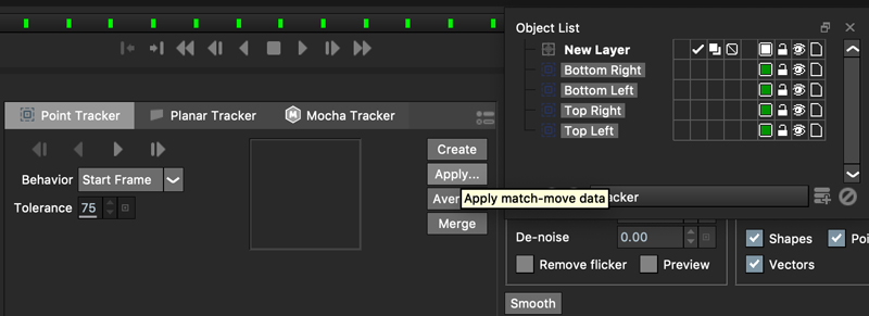
To apply an insert using the data:
Feed an the insert image and the previously created tracker node into a Transform node:
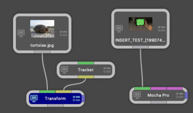
Select the tracking layer from the Transform list:

You can then use a 'Composite' or 'Math Composite' to combine the corner pinned image over the top of the background image:

And adjust the corner pin settings to fit the background:
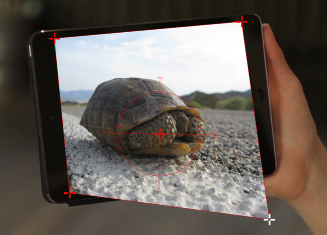
The image should now follow the background source as expected.
Exporting tracks to Mistika
You export Mocha planar tracking data to Mistika as a set of corner pin tracks by choosing Mistika Point Tracker (*.trk) from the Export Tracking Data dialog.
You can import your saved Mistika Point track data from the File menu.
Exporting Tracks to Nuke
This section explains how to export tracking data in a format readable by Nuke, how to import the data into Nuke and how to use it for match move, corner pinning and stabilization tasks.
Track an object in the usual way, and use AdjustTrack to correct for any drift if necessary. The exported tracking points will be the four corner points of the Surface, so you should position these appropriately.
Press the Export Tracking Data button on either the Track or AdjustTrack tabs.
From the "Nuke (The Foundry) category, choose
Nuke Ascii (*.txt)and click 'Save' to save the script to disk.
In Nuke, append a tracker to the background clip, e.g. by selecting the node and pressing tab, then typing 'tracker' and finally selecting the 'Tracker' node in the list of nodes.
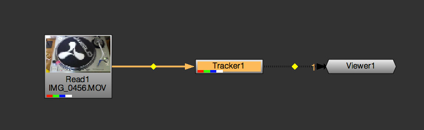
In the tracker properties window, select the animation submenu button for Tracker 1, then choose File | Import Ascii… in the menu.
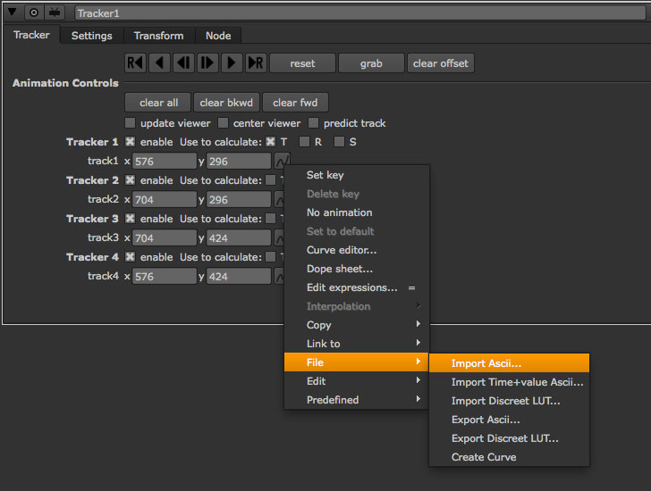
On the import Ascii dialog, press the folder button next to the file name, browse to the file you exported, select it, click 'Open' and then click 'OK'.
Repeat these steps for tracker 2, 3 and 4.
Exporting to Nuke 7 Tracker Node
If you’re in Nuke 7 or above and you don’t want to go through the process of exporting out your ascii files, you can instead export to the Nuke Tracker Data - 7.0+ (*.nk) node.
If you choose Copy to Clipboard you can immediately switch over to Nuke and Paste the data. Alternatively you can import your saved Nuke Script from the File menu.
Exporting Corner Pin tracks to Nuke Corner Pin Node
You can export a Corner Pin straight to the clipboard or to a .nk script by choosing Nuke Corner Pin (*.nk) from the Export Data dialog.
If you choose Copy to Clipboard you can immediately switch over to Nuke, select the node you wish to apply the corner pin to and Paste the data. Alternatively you can import your saved Nuke Script from the File menu.

Exporting to Nuke Mesh Tracker node
The PowerMesh to Nuke Tracker creates a single Nuke tracker node with individual tracker points representing every vertex in the PowerMesh.
This versatile export means you have access to numerous tracking points across your scene without having to set up individual tracks or corner pins.
You can export a PowerMesh-based Nuke Tracker straight to the clipboard or to a .nk script by choosing Nuke PowerMesh to Tracker Data (*.nk) from the Export Data dialog.
If you choose Copy to Clipboard you can switch over to Nuke, select the node you wish to apply the corner pin to and Paste the data. Alternatively you can import your saved Nuke Script from the File menu.
Exporting Tracks via the Nuke plugin interface
You can also export linked or baked tracks directly from the Mocha Pro OFX plugin interface in Nuke. See The Data Export Tab for more details.
Exporting Tracks to Blackmagic Fusion
This section explains how to export tracking data in a format readable by Fusion, how to import the data into Fusion and how to use it for match move, corner pinning and stabilization tasks.
Track an object in the usual way, and use AdjustTrack to correct for any drift if necessary. The exported tracking points will be the four corner points of the Surface, so you should position these appropriately.
Press the Export Tracking Data button on either the Track or AdjustTrack tabs.
From the "Fusion (Blackmagic)" category, choose 'Fusion Tracker Data (*.comp)' and click 'Save' to save the script to disk or 'Copy to Clipboard'
In Fusion, open the .comp file or paste from the clipbaord then drag the tracker node into the right view.

Now import the clip that you want composited onto the background and tie the output of the clip to the input of the tracker node.

In the settings of the tracker node, select the 'Operation' tab and select either 'Corner Positioning' or 'Match Move' to composite the insert clip on top of the background. Notice that you can switch 'Position', 'Rotation' and 'Scaling' on and off for different effects.
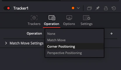
Exporting Tracks to Inferno, Flame, Flint, Smoke and Combustion
This section explains how to export tracking data in a format readable by Autodesk Inferno, Flame, Flint, Smoke and Combustion.
Exporting Flame Axis data
Currently Mocha can only export Flame Axis tracking data via the Gmask Tracer node.
Track an object in the usual way, and use AdjustTrack to correct for any drift if necessary.
The exported tracking points will be the four corner points of the Surface, so you should position these appropriately.
Press the Export Tracking Data button on either the Track or AdjustTrack tabs.
From the "Flame (Autodesk" category, select 'Flame Axis (.mask)' and save the file to disk (There is currently no clipboard support for mocha data in Flame).
Importing into Flame
To import the data into Flame:
Create a new Gmask or Gmask Tracer node in Batch
Click the Load Node Button:
 +
+Navigate to the saved '.mask' file and open it
You should then see the axis in the Flame viewer output.
You can now wotk with the Axis nodes via the Gmask Schematic:

Exporting Flame Tracking ASCII Data
Track an object in the usual way, and use AdjustTrack to correct for any drift if necessary.
The exported tracking points will be the four corner points of the Surface, so you should position these appropriately.
Press the Export Tracking Data button on either the Track or AdjustTrack tabs.
From the "Flame (Autodesk" category, select 'Flame Point Tracker Data (*.ascii)' as the format, and save this to a file.
Next select the 'Flame Stabilizer Data (*.ascii)' export and save this to another file.
Importing into Inferno, Flame, Flint or Smoke for Corner Pinning
Firstly, we will set-up a corner-pin composite in the Action module, to reproduce the basic compositing operation.
Enter Action and delete the default Axis and Image nodes.
Create a new Bilinear Surface. Tap on bilinear1 then press ~ to view its settings. Go to Surface then click the S button next to Track.

You should now be in the familiar stabilizer module. For this example we are doing a corner-pin so we will need to use all four trackers.
Tap Tracker 1 then press 'Imp' under 'Track Y'.
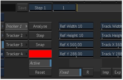
Now browse to the corresponding file, e.g. xxxx_top_left.ascii. The files correspond to trackers as shown below.
You should see the marker for Tracker 1 move into the correct position.
Repeat the process for the other three trackers, making sure that you use the correct files as shown in above. You should also mark each tracker as Active if it is not already.
Tap Return to return to Action, and you should now see your finished corner pin.
Importing into Inferno, Flame, Flint or Smoke for Stabilization
An alternative use for the tracking data is for stabilization. You can use the Stabilizer module to do 1-, 2-, 3- or 4-point stabilization. In this example, we will do a 1-point stabilization to stabilize for position only, using the center point.
Enter the Stabilizer module. Click the Imp button under Track Y, as for the Corner Pin.
Select the _center file, in my example this is PDA_center.ascii. You should now see the key-frames loaded and be able to process
If you want to use more points to stabilize zoom, rotation, affine and perspective moves, just load the corner tracks as described in the Corner Pin section.
Exporting Tracks to Assimilate SCRATCH
To import data into SCRATCH requires SCRATCH v7 or later.
To import the data into Assimilate, do the following:
Enter the SCRATCH player with the background shot

Create a scaffold with a the image you want to insert (Make it a bicubic since you want a 4-corner pin deformation)
Either load the background shot into Mocha and track or send the shot from SCRATCH to Mocha by creating a custom command
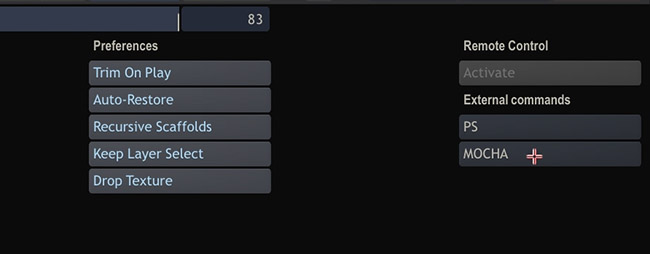
Track an object in the usual way, and use AdjustTrack to correct for any drift if necessary. The exported tracking points will be the four corner points of the Surface, so you should position these appropriately.
Press the Export Tracking Data button on either the Track or AdjustTrack tabs.
Select from the "SCRATCH (Assimilate)"" category, choose 'SCRATCH Corner Pin Data (*.txt)' as the format, and save this to a file or copy to clipboard
Switch back to SCRATCH, select the scaffold with the bicubic and click on TRACK.
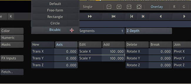
Once on the TRACKING interface you will see "Paste Mocha data" highlighted, which is detecting that you have Mocha data on the clipboard.
Click on "Paste Mocha data" and the data will be applied to the element.
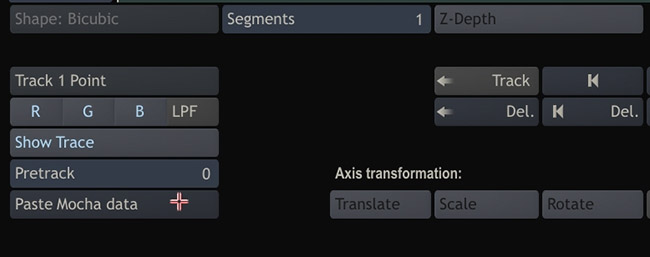
Exporting Tracks to SGO Mistika
The Mistika export format provides 4 corner pin track points.
To export tracking data to the Mistika:
Click the Export Tracking Data… button on the Track module, or AdjustTrack module
From the "Mistika (SGO)" category, choose
Mistika Point Tracker File (*.trk). Save the file to disk.
Mistika at this time does not support clipboard pasting of the track data.
There are two ways to import the data to Mistika:
Corner Pin Insert
Applying Corner Pin is usually done in the Comp3D effect.
Ensure you have the correct layer active in the Comp 3D control panel
Open up the track controls and choose
Path > LoadFind and load in your saved Mocha track file
You may have to delete an errant 'T0' tracker that Mistika adds by default.
Select
Apply To > Corner PinChoose
Apply > Moveand the tracking data will be applied to the layer.
| You will have to move the CTI to refresh the viewer once you have applied the tracking data |
Transform
Any clip or effect that supports the Tracking tab can use Mocha track data.
Open up the track controls and choose
Path > LoadFind and load in your saved Mocha track file
Choose the track point(s) you wish to use.
Choose the type of data you wish to apply in Apply To. Note, you will have to have more than one tracker selected to use Rotation and Size.
In Apply, select the type of move you wish to do, eg. Move for matchmoves or Stabilize for stabilization.
Some effects or shapes only support translation data. In these situations Rotation and Size will have no effect.
Exporting Tracks to HitFilm
You can export HitFilm transform and corner pin data directly to a HitFilm Composite Shot file.
Exporting tracks to HitFilm is very similar to exporting HitFilm Camera solves or Shapes:
Select a layer and go to "Export Tracking Data…"
From the "HitFilm (FxHome)" category, choose HitFilm Corner Pin with Motion Blur or HitFilm Transform Data
Click Save and choose a file name
Importing is done via the Compositing section in HitFilm:
In HitFilm go to your Composite section
Choose Import > Composite Shot
Select the saved HFCS file from Mocha
HitFilm will then load the Composite Shot with the footage you tracked in Mocha and layers with either a Quad Warp (for corner pin) or the layer with transform animation applied (for Transform).
You can then either relink the media in the composite file to the desired insert, or copy the Effect or Keyframes to the desired media in your existing composite.
Exporting 2D Alembic Data
| This section refers to exporting 2D Alembic tracking data, not 3D data. To export solved 3D meshes to Alembic, see the Exporting Camera Solves section. |
Alembic Mesh Data
The Alembic Mesh format is used to export PowerMesh tracks to a range of different software.
Mocha exports a flat mesh with X and Y coordinates for each mesh vertex generated via the Mesh parameter in the Track module.
The export also includes a camera to make sure the mesh is projected correctly to the original footage dimensions.
Alembic meshes also contain UV mapping so you can easily warp a texture to the mesh without needing to set them up yourself.
| Note that this particular Alembic format, while 3D, does NOT contain Z information in the mesh. We are not calculating depth in this export, only the positions of the vertices on a tracked plane. |
Alembic is a versatile format that can be imported into many different compositors, such as:
Nuke
Flame
Fusion
HitFilm
Along with 3D applications such as:
Cinema 4D
Maya
3ds Max
Blender
And so on.
Exporting Alembic Meshes
To export an Alembic mesh, do the following:
Track a layer using PowerMesh by selecting the "Mesh" parameter and generating a mesh. See the PowerMesh section for more details on Mesh tracking.
Select the "Export Track…" option in the Track module or the File menu
From the "Alembic (2D)" category, choose "Alembic 2D Mesh Data (.abc)" from the list of options
Enter a Reference Frame into the "Ref Frame" field if you want to change where the UV coordinates start from. By default the number in the field is the frame you generated the mesh on.
Click Save and choose a file name.
Importing Alembic Meshes to Nuke
Nuke imports Alembic via the "ReadGeo" node:
Import your source footage to the nuke project
Create a ReadGeo node
Open the exported Alembic file via ReadGeo’s file browser
Change the import parameters if necessary
ReadGeo will then ask how you want to set up the camera and geometry nodes.
You can use the ReadGeo in combination with the Scanline Renderer node to composite warped textures over the top of the original footage:
Create a Scanline Renderer node in the node graph
Feed in the ReadGeo, Camera and Source image into the inputs of the Scanline Renderer node. If you view the node, the mesh should now be correctly projected over the top.
Add an image or material to the 'img' input of the ReadGeo node. This will then project the texture onto the Mesh.
Scrubbing the timeline should show the texture warping to the mesh faces over time.

Importing Alembic Meshes to Fusion
Fusion imports Alembic via the "Alembic Scene" import:
Import your source footage to the Fusion project
Create an ABC node chain by importing the Alembic file via File > Import > Alembic Scene…
Change the import parameters if necessary
Fusion will then set up an ABC node with the geometry and camera fed into it.
You can use the ABC node in combination with the Renderer3D node to composite warped textures over the top of the original footage:
Create a Renderer3D node in the node graph
Feed in the ABC into the input of the Renderer3D node.
Merge the Renderer3D node over the top of your source footage node. If you view the Merge node, the mesh should now be correctly projected over the top.
Add an image or material to the input of the mesh node that is the same as your mocha layer name. This will then project the texture onto the Mesh.
Scrubbing the timeline should show the texture warping to the mesh faces over time.

Importing Alembic Meshes to Cinema4D
You can open an Alembic file as a project in Cinema4D.
Go to File > Open and choose the exported Alembic file.
Click the view camera icon in the Camera layer to view the mesh through the camera
Create a new Background object
In the Materials panel create a new basic material
Import your source footage to the material as a texture
In the Viewport options for the material, turn on "Animate Preview"
Drag the material to the Background layer
You should now see the Mesh lining up with the source footage.
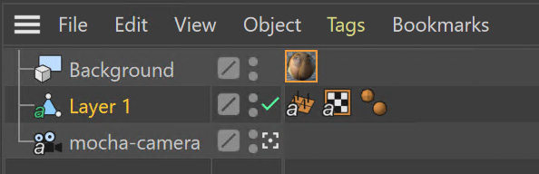
Alembic Vertex Transform Data
Similar to meshes, this alembic format provides just the transform information for the vertices in the mesh (along with the camera).
Vertex transforms can be interpreted by supporting hosts in different ways.
For example, in Nuke they are imported as a point cloud, but in Blender they may import as nulls linked to transforms.
Exporting 2D Tracking Data to SynthEyes
You can export planar tracking and PowerMesh tracking data to the SynthEyes SNI format without solving the camera first.
Track your shot as required in Mocha
Select
Export Track…from the Track module orExport Data…from the File menuFrom the "SynthEyes (Boris FX)" category, choose
SynthEyes 2D Tracker Data (*sni)from the dropdown and click save
To import the data, either open the SNI file directly from File > Open menu in SynthEyes, or choose Merge to merge your tracking data to the existing project.
Exporting Stereo Tracking Data
Exporting stereo Track data from Mocha is the same as exporting in mono mode, however when you are in multiview mode you can choose the view you want to export.
Select a layer
Click "Export Tracking Data…" from the Track module or choose the option from the file menu (File | Export Data…)
Select the Application you wish to export to
Select the view you want to export (or check "Export all views" if it is available for that export format)
Choose whether you want to export the currently selected layer, all visible layers or all layers
Click "Copy to Clipboard" or "Save" depending on your preference. Note that some exports only allow you to save the data.
Legacy Track Data Formats
This section outlines some of the older formats that may still be in use, but are categorised as Legacy.
To reveal Legacy formats in the Export dialog, turn on the Legacy checkbox.
Exporting Tracks to Final Cut Pro or Final Cut Express
This example illustrates how to export Basic Motion data to Final Cut Pro or Final Cut Express, and use it to matchmove one clip to another, with translation, rotation and scale.
Track an object in the usual way, and use AdjustTrack to correct for any drift if necessary. The exported tracking points will be the four corner points of the Surface, so you should position these appropriately before export.
Press the Export Tracking Data button on either the Track or AdjustTrack tabs.
Turn on the 'Legacy' filter in the Export Dialog to Reveal the Final Cut (Apple) formats.
Choose either the Final Cut Basic Motion or the Final Cut Distort options.
Final Cut Distort:
The distort option exports the 4 point x, y information from either the adjusted track or the raw track. The points exported are the four corners of the surface.
Final Cut Basic Motion:
The basic motion option exports x and y positions as well as the scale and rotation for the whole surface. The position exported is the center of the surface.
Now click Save. This will display a file browser; you need to select a filename and directory for the files to be saved. By default, the files will take the name of the layer, so for a layer name Track_Layer this export produced a file named:
Track_Layer.xml
Now open the Final Cut project where you want to use the tracking data. To import the XML file in Final Cut Pro, click File | Import | XML…. In Final Cut Express, click File | Import | FCP XML from iMovie…
You will now see a new clip in your bin, named 'Mocha distort – layer_name' or 'Mocha basic motion – layer_name'. If your original footage was a QuickTime file, then the new clip in Final Cut will point to this footage. If it was an image sequence, the clip will be connected to the first frame of the sequence, stretched to the duration of the whole clip.
In most situations, you want to apply the tracking data to a different clip in your timeline. To do this, you can copy and paste the data from the imported clip onto any other.
Drop your imported clip into the timeline, then select it and press Cmd-C to copy it to the clipboard. Now select the clip you want to apply the tracking data to and press Opt-V (Paste Attributes). You will see a dialog asking you to choose which data to paste.
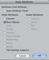
Depending on the kind of data you exported, tick either 'Basic Motion' or 'Distort' and untick all the other boxes.
You should now see the clip following you tracked.
Using Tracks for Stabilizing in Final Cut
To use our tracking data for stabilization in Final Cut, follow the same procedure as for a basic motion export, but tick the Invert checkbox in the export dialog.
Now when you import the XML file into Final Cut, you should have a fully stabilized clip. You can also copy the stabilized data onto another clip using Copy and Paste Attributes as before.
Troubleshooting Tracking Export to Final Cut
Many issues of track misalignment can be corrected by choosing the right film type, frame rate and interlacing settings in our software. These controls are on the Clip page in the Film, Interlaced and Time tabs.
The layer doesn’t line up in Final Cut
If the layer doesn’t line up but the overall motion looks right, the most likely problem is mismatched pixel aspect ratio (PAR). In Final Cut, check the sequence settings to confirm the correct PAR for the clip, then use the equivalent setting when tracking in our software. If you have already tracked with the wrong film type setting, you will need to re-track after changing it. The table on the next page shows the corresponding settings between Final Cut and Boris FX products.
Although film types are included in our software for anamorphic HD sizes (DVCPRO HD and HDV), you are unlikely to need to use them as QuickTime will normally apply the anamorphic scaling and our software will treat the video as full HD.
The layer lines up on the first frame, but then it drifts
This is usually caused by a frame rate mismatch. Check that the frame rate and interlacing settings match between final Cut and our software.
The layer appears much wider or thinner than it should
This can be caused by a mismatch in the Final Cut Anamorphic setting. If you are working with anamorphic footage, ensure that you have the 'Anamorphic' setting checked in your Final Cut sequence settings, and in the clip properties. You also need to use one of the anamorphic film types when tracking: any of the film types with 'Anamorphic' in the name should give correct results when importing the data into Final Cut.
Exporting Tracks to Apple Motion
Track an object in the usual way, and use AdjustTrack to correct for any drift if necessary. The exported tracking points will be the four corner points of the Surface, so you should position these appropriately.
Press the Export Tracking Data button on either the Track or AdjustTrack tabs.
Turn on
Legacyin the Export Data dialog to reveal the Motion (Apple) formatsNext, choose 'Motion basic transform(* .motn)' or 'Motion corner pin (*.motn)' and click 'Save' to save the file.
Inside Motion, you can either choose to open the exported file as a new project or drag it into an existing project. You will see a Group containing the footage you tracked as well as a blue solid called "Surface".
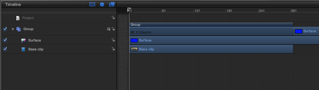
Then take the following steps to insert your footage:
Drag the desired footage or image to the group, above the surface
Go to Motion Tracking in Behaviors and drag the Match Move behavior onto your insert
If the surface layer does not automatically apply to the behavior, drag the surface layer onto the Match Move behavior
If you are just using transform, Match Move defaults to this option and you can set transform, scale and rotation
If you are using corner pin, select the 'Four Corners' option from the 'Type' drop down.
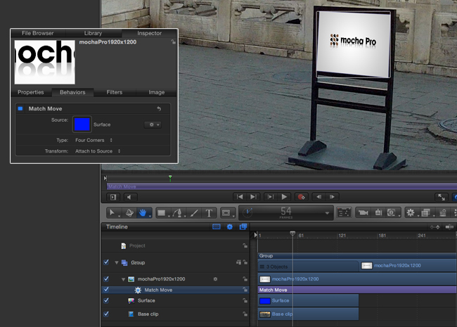
Troubleshooting Tracking Export to Apple Motion
Many issues of track misalignment can be corrected by choosing the right film type, frame rate and interlacing settings in our software. These controls are on the Clip page in the Film, Interlaced and Time tabs.
The layer lines up on the first frame, but then it drifts
This is usually caused by a frame rate mismatch. Check that the frame rate settings match between Motion and Mocha.
The layer tracks correctly but is offset or scaled oddly
This is normally due to the layer you are inserting not being the same frame size as your project media. You can fix this by either changing the insert to fit the dimensions, or scaling the insert inside motion to match the dimensions. If you are going to scale the layer to fit, you should do this step before you apply Match Move.
Exporting Tracks to Apple Shake
This section explains how to export tracking data in a format readable by Apple Shake, how to import the data into Shake and how to use it for match move, corner pinning and stabilization tasks.
Track an object in the usual way, and use AdjustTrack to correct for any drift if necessary. The exported tracking points will be the four corner points of the Surface, so you should position these appropriately.
Press the Export Tracking Data button on either the Track or AdjustTrack tabs.
Turn on
Legacyin the Export Data dialog to reveal the Shake formatsNext, choose 'Shake Tracking Data (*.shk) and click 'Save' to save the script to disk or 'Copy to Clipboard' to simply copy-and-paste the data into Shake.
Now let’s use that data in Shake. To load the tracking data in a file into an existing Shake Script follow these steps:
In the File menu, select ‘Add script'.

Navigate to the Shake script file you exported and select it.
If you have the data on your clipboard, simply press Ctrl/Cmd+V or right-click and choose 'Paste'.
Three nodes will now appear in your script: Stabilizer, MatchMoveLayer, and CornerPinLayer.
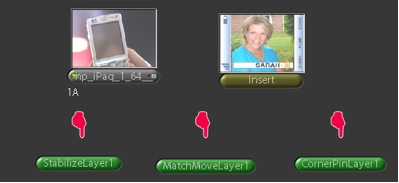
At this point you have successfully imported your tracking data from Mocha into Shake. But what exactly did you import? Let’s start with the MatchMoveLayer layer.

The MatchMoveLayer is used to apply the tracking data to a foreground element that you wish to matchmove to a background. It consists of two inputs, the background and the foreground. The foreground element will be the element you wish to apply the match moving data to. The foreground is connected to the left side input of the node while the original tracked background element goes into the right hand side.

The next node is the CornerPinLayer node. This node has a single input and works just like the left input of the MatchMoveNode.
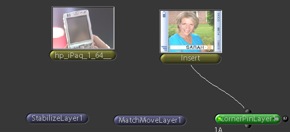
It takes your foreground element and applies the scaling, rotation, and translation data to it and prepares it for compositing into your next layer.
The last exported node is the Stabilizer Node. Just as the name implies, it takes all of the exported tracking data and uses that data to stabilize your input clip.
With this node, for example, you may apply this data to the background element you tracked to make for an easier composite.
Now that you have successfully exported and imported your data into Shake you are ready to continue working on your project.

Importing into Autodesk Combustion
First, follow the steps outlined in "Exporting Flame Tracking ASCII Data" above.
In Combustion, create a layer with the foreground graphic and set the layer shape to 'Four-Corner'.
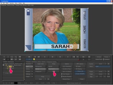
Now select all four corners of your layer, enable the 'Tracker' tab and select 'Import Tracking Data.'
Import the single Ascii file with the stabilizer tracking data.
Activate the insert layer visibility and you will see that the insert layer is now tracked to the background element, even though the image is not sized correctly yet. Select all trackers and set the mode to 'Absolute' to resolve this.
If you prefer to import your data one point at a time you can instead select one track point and import the Ascii file with the corresponding tracking data. Remember to switch to 'Absolute' mode once all data has been imported.
Exporting Tracks to Boris FX Plugins
You can export either Corner Pin or Center Point data out to any Boris FX plugin that supports motion tracking data. These include effects such as the BCC Corner Pin effect and Witness Protection.
The files are import only, so you can’t copy them to the clipboard. You can save the data as a text file and import it.

Importing the track is as simple as locating the Motion Tracker section of your BCC plugin and clicking either the "L" button or selecting "Load…" from the Import-Export dropdown, depending on the plugin you are using.
Exporting Tracks to Avid DS
| It is important that the clip length, frame rate, frame size, interlace mode, pulldown mode and pixel aspect ratio in the project match the corresponding settings in Avid DS project where you plan to use the data. You can change the frame rate and pixel aspect ratio settings in the Film and Time sections of the Clip tab. |
This section explains how to export tracking data in a format readable by Avid DS.
Track an object in the usual way, and use AdjustTrack to correct for any drift if necessary. The exported tracking points will be the four corner points of the Surface, so you should position these appropriately.
Press the Export Tracking Data button on either the Track or AdjustTrack tabs.
From the "Avid DS (Avid)" category, select 'Avid DS Tracking Data (*.fraw)' as the format, and save this to a file. This stores the x/y coordinates of the four surface points defining the track in eight .fraw text files using the following naming convention:
...._R1x.fraw Lower left X coordinate

...._R1y.fraw Lower left Y coordinate


...._R2x.fraw Lower right X coordinate

...._R2y.fraw Lower right Y coordinate


...._R3x.fraw Upper left X coordinate

...._R3y.fraw Upper left Y coordinate


...._R4x.fraw Upper right X coordinate

...._R4y.fraw Upper right Y coordinate
Where "…." is replaced by the name of the exported layer.
On your DS v10.x system, create a Tracker node and open the Animation Editor for it.
In the left window check the little Blue Animation box to the left of R1x, R1y, R2x, R2y, R3x, R3y, R4x, and R4y.
Now right-click "R1 Tracker Y" and select "Import tracking coordinates".
Navigate to the folder containing the eight FRAW files that Mocha created and DS will load them. If you have an older version of DS then you will have to load each of the eight FRAW files individually.
Exporting Tracks to Quantel generationQ systems
To import data into the Quantel requires Boris FX’s TrackImport plug-in for Quantel.
You can import tracking data into Quantel systems by using Boris FX’s TrackImport plug-in.
Track an object in the usual way, and use AdjustTrack to correct for any drift if necessary. The exported tracking points will be the four corner points of the Surface, so you should position these appropriately.
Press the Export Tracking Data button on either the Track or AdjustTrack tabs.
Select 'Quantel Corner Pin Data (*.xml)' as the format, and save this to a file.
In the Quantel system, select the TrackImport plug-in, and use the plug-ins file browser interface to select the tracking data file to import. Then click 'Settings' and choose 'Tracker' in the settings window and click 'Save'.
The tracking data can now be used in a manner identical to tracking data generated within the Quantel system.
Exporting Tracks to MochaBlend
To export tracking data to the Good Spirit Graphics MochaBlend plugin, click the Export Tracking Data… button on the Track module or AdjustTrack module.
You can export the tracking data by either saving it to file, or copying to the clipboard.
To import the tracking data into the plugin, you start by selecting an available Data slot and then either paste from the clipboard or open the exported file:
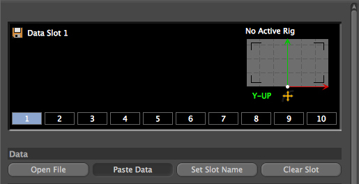
Once imported, you can then adjust your scene to fit the data. It is important to make sure you check the warnings and correct any relevant items before setting up your rig:
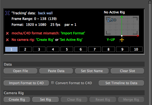
If there is a warning about format mismatch, click the green "Import Format" link in the MochaBlend window
If there is a warning about no camera rig, click the green "Create Rig" or "Set Active Rig" according to your needs
Finally make sure that you click the "Set Timeline to Data" if your project timeline is different from the frame range you tracked in Mocha
You can then go ahead and tweak individual settings in the MochaBlend plugin. See MochaBlend documentation for further information on working with tracking data in the plugin.
Exporting Mattes and Clips
| Some export formats listed below are not available for Mocha HitFilm or Mocha AE. For a full comparison of features, please refer to the comparison chart online. |
| Some shape data formats are not supported across 360 seams and poles in Equirectangular space and may not export as expected. |
Exporting Rendered Shapes
| This feature is only available in Mocha Pro |
When your roto work is complete and you would like to export your mattes, choose the menu item File → Export Rendered Shapes… to be guided through the rendering process.
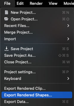
The render dialog will give you options to choose either:
The currently selected layers
All visible layers
All the layers in the project.
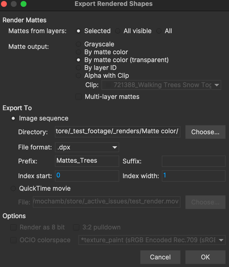
Matte Output Options
The type of matte you want to export can vary depending on your workflow:
Grayscale: The default grayscale mattes
By matte color: Export with the matte colors defined in layer controls
By matte color (transparent): Export with the matte colors, but overlaid with color add. This is useful for exporting mattes that you want to split into RGB color channels.
By layer id: Export mattes colored by their layer order.
Alpha with Clip: Export the matte as an alpha applied to the selected clip. By default this is the source clip, but can also be any imported or rendered clip that matches the properties of the source clip.
Multi-Layer Mattes: For use with EXR and SXR files. You can export each layer matte (and the source clip) to separate EXR channels instead of combined mattes.
Export To
The export options for Image Sequences and QuickTime movies.
For Image Sequence you have the following options:
Directory: The directory where you want to export your image sequence.
File Format: A list of available image formats to render to
Prefix: The name of the clip to go in front of the frame numbers
Suffix: The name of the clip to go after the frame numbers (blank by default)
Index Start: The number to start the exported sequence from. By default this is the first frame in the timeline
Index Width: The number of padding zeroes to use.
Exporting QuickTime movies
Which video file format reader you are using will determine the export handling of clips:
Using QuickTime: Choosing 'QuickTime movie' will bring up the legacy QuickTime export options when you click OK.
Using GStreamer: Choosing 'QuickTime movie' will bring up the GStreamer export dialog when you click OK. This currently only supports ProRes[1].
Additional Options
Render as 8-bit: Convert the matte to 8-bit
3:2 pulldown: Check if rendering interlaced mattes with 3:2 pulldown
OCIO colorspace: Render the mattes using the target colorspace.
Exporting Matte Colors as Transparent Channels
The option Matte Colors (transparent) is generally used to color-add overlaying mattes so you can split out their individual RGB channels in your compositor.
In order to do this correctly, each matte you want to render should be in a pure RGB color (i.e Pure Red, Green or Blue.).
So you don’t have to set this up with the layer matte color swatch, there is an option in the Layer Controls right-click menu:
Select the layers you want to change to a specific pure RGB color
Right-click
Choose the Matte Color menu and select one of the following colors:
Pure Red
Pure Green
Pure Blue
Exporting Stereo Rendered shapes
The render dialog also allows you to render to single footage streams or a combined stream via EXR.
Go to File | Export Rendered Shapes…
Choose the mattes you want to export in the top radio buttons.
Selected: The last selected layer.
All Visible: Only the layers that have visibility turned on in the layer controls
All: All layers except ones you have specifically deactivated.
Choose the Color Output:
Grayscale: The default black and white mattes with feather.
By matte color: The same as Grayscale, only the mattes are colored according to what you defined each layer matte color to be in the Layer Controls.
By layer ID: A special use case for those that want the mattes to be colored by their layer ID.
Under "Export Views" select the render option you want:
Current Only: Renders the current view you have selected.
To single footage stream: Renders all views to a single file. You are limited to rendering to EXR or SXR.
To separate footage streams: Renders the views as individual sequences.
Then choose your file path and render format.
If you have chosen to render the current view or separate footage streams, the view abbreviation will be suffixed to the rendered export automatically, so there is no need to define this in the file name.
Exporting as Adobe After Effects Mask Data
| It is important that the clip length, frame rate, frame size, interlace mode, pulldown mode and pixel aspect ratio in the project match the corresponding settings in the After Effects project where you plan to use the data. You can change the frame rate and pixel aspect ratio settings in the Film and Time sections of the Clip tab. |
The Mocha shape data is converted to After Effects masks via the Mocha AE plugin built into After Effects.
When you are ready to export, select Export Shape Data button. The export dialog will open, filtered to just Shape data.
From the
After Effects (Adobe)category, Choose Adobe After Effects Mask Data
Choose if you want to export the currently Selected layer, All visible layers, All layers or a specific layer
Choose whether you want to export the layer ranges as opacity keyframes by checking the
Keyframe Layer Rangescheckbox. This is on by default.When you have made the right selection, click Copy to Clipboard, then switch to After Effects.
In After Effects, import the same footage and ensure that the frame rate and pixel aspect ratio are the same as those used when generating the shape.
You can change these values in After Effects by selecting File | Interpret Footage | Main….Bring the footage into a composition, then select
Edit > Paste Mocha Mask. Each shape exported will appear on the layer as a separate mask.
| Mocha can also paste using a legacy plugin called the mMcha shape plugin. This is now obsolete as all shape rendering functions are available via the Mocha Pro and Mocha AE plugins. |
Exporting Adobe Premiere Pro CC Masks
Exporting shapes to Adobe Premiere Pro CC is very similar to exporting shapes to After Effects
Select a shape and go to "Export Shape Data…"
From the
Premiere (Adobe)category, choose Adobe Premiere shape dataChoose if you want to export the selected layer, all visible layers or all layers
Copy to the Clipboard
Importing is just as straightforward:
In Adobe Premiere Pro CC, select your clip on the timeline
In the Effects panel, click on Opacity
Paste the data using CMD/Ctrl + V or right-click and choose Paste
You can also apply the masks to most effects, by adding the effect to your clip, selecting the effect in the Effects panel and pasting.
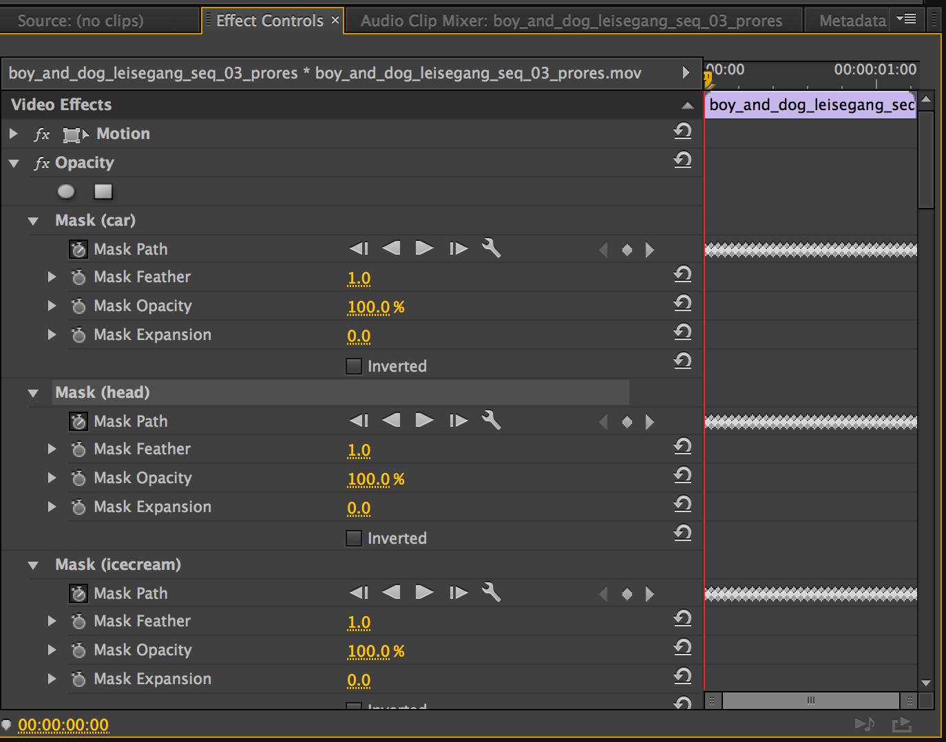
Exporting Flame Gmask and Flame Gmask Tracer data
Mocha can export masks as either direct Flame Gmask nodes or Flame Gmask Tracer nodes.
These formats are broken down into:
Flame Tracer [Shape + Axis] (.mask): This is a Gmask Tracer node split into the keyframed shape data on a Gmask and the separate tracking data in an Axis. This makes it easier to change the mask data in Flame or attach other nodes to the Axis tracking data.
Flame Tracer [Basic] (.mask): This is a Gmask Tracer node with the Mocha tracking data and shape keyframes combined into Gmask keyframes without an axis.
Flame Gmask Script (.gmask): This is a straight Gmask node with the Mocha tracking data and shape keyframes combined into keyframes without an axis.
You can select the type from the "Export Data" dialog under the Flame (Autodesk) category.
Choose whether you want to export the layer ranges as transparency keyframes by checking the Keyframe Layer Ranges checkbox. This is on by default.
Importing into Flame
To import the mask data into Flame:
Create a new Gmask or Gmask Tracer node in Batch
Click the Load Node Button:
+Navigate to the saved '.mask' file and open it
You should then see the Gmask results in the Flame output.
If you are using GMask Tracer, you can view the Axis or Gmask nodes via the Gmask Schematic:

Exporting Shapes to HitFilm
You can export Mocha shape data directly to a HitFilm Composite Shot file.
Exporting shapes to HitFilm is very similar to exporting HitFilm Camera solves:
Select a shape and go to "Export Shape Data…"
Choose HitFilm [Transform & Shape] from the
HitFilm (FxHome)categoryChoose if you want to export the selected layer, all visible layers or all layers
Click Save and choose a file name
Importing is done via the Compositing section:
In HitFilm go to your Composite section
Choose Import > Composite Shot
Select the saved HFCS file from Mocha
HitFilm will then load the Composite Shot with the footage you tracked in Mocha and layers with shape masks.
Exporting Roto, RotoPaint and SplineWarp Nodes to Nuke
You can export a Roto, RotoPaint or SplineWarp node straight to the clipboard or to a .nk script by choosing Nuke Roto Paint (*.nk) from the Export Shape Data dialog.
To export shapes to Nuke:
Select a shape and go to "Export Shape Data…"
Choose one of the Nuke exports from the
Nuke (The Foundry)categoryChoose if you want to export the selected layer, all visible layers or all layers
If you choose Copy to Clipboard you can immediately switch over to Nuke, select the node you wish to apply the shape data to and Paste the data.
Alternatively you can import your saved Nuke Script from the File menu.

You have the option of exporting Basic Roto data which bakes the keyframes, or Transform and Shape data which separates the tracking data from the manual keyframes.
The latter makes the data less heavy and is only supported in Nuke 6.2 and above.
The SplineWarp node exports each layer as a joined set of splines with the spline keyframes separate from the tracked data (which is set in each curves transform).
For example if you only have 1 tracked layer to export, Mocha will export that layer to SplineWarp as two joined splines in A.
You can then modify the second spline for the warp, or delete it and choose another.
Exporting Shape Data to Blackmagic Fusion Shapes
To export shape data to the Fusion shape format:
Click the Export Shape Data… button in the Track module or Export Data… from the File menu.
From the
Fusion (Blackmagic)category, selectFusion Poly Shape DataChoose whether you want to export the layer ranges as visibility keyframes by checking the
Keyframe Layer Rangescheckbox. This is on by default.You can export the shape data by saving it to file or by copying it to the clipboard
To import the shape data into Fusion, either paste directly into the Fusion Flow View or open the comp file from the file menu.
The Mocha layers will come in as separate nodes into the Flow View.
Fusion MultiPoly Shapes
If you are using Fusion 19 or above, you can also choose the Fusion MultiPoly Shape Data export to export all your shapes to a single node.
This greatly reduces the number of nodes in Fusion when working with many layers in Mocha.
Exporting Shape Data to Silhouette Shapes
To export shape data to the Silhouette FXS shape format:
Click the Export Shape Data… button in the Track module or Export Data… from the File menu.
From the
Silhouette (Boris FX)category, selectSilhouette Shape Data. You can export the shape data by saving it to file or by copying it to the clipboardTo import the shape data into Fusion, either paste directly into the Fusion Flow View or open the comp file from the file menu.
To import the shape data into Silhouette, create a Roto node in the existing session and the import the data from File → Import… → Silhouette Shapes menu option, or paste from the clipboard:
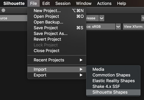
Legacy Shape Data Formats
This section outlines some of the older formats that may still be in use, but are categorised as Legacy.
To reveal Legacy formats in the Export dialog, turn on the Legacy checkbox.
Exporting as Mocha shape for Final Cut
The Mocha shape plug-in will import the following data into Final Cut:
One or more shapes, which may be either Bezier or X-Spline
The 'plane' that was generated by the Planar Tracker. This defines the overall movement of the shape(s)
Shape point keyframes set in the project
Per-point feathered edges
If you wish to export a single layer, select it before proceeding with the export.
When you are ready to export, select Export Shape Data button. On the dialog that opens, choose if to export the selected layer, all visible layers or all layers.
When you have made the right selection, click Save and select a destination to save the XML file to, then switch to Final Cut.
In Final Cut, import the XML file by CTRL-clicking in the project asset window.
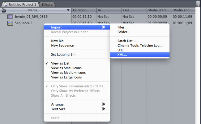
Select 'Import', then 'XML…' and finally select the XML file that you exported.
Accept all the defaults in the 'Import XML…' dialog.
Your Mocha shape sequence will now appear in your list of project assets.

To use the shape to composite the rotoscoped object over a new background, simply place the Mocha shape sequence in a video track above the background sequence.

Additional controls
If you want access to the actual matte, individual layers of the matte or control that affect the appearance of the matte, double click on the Mocha shape sequence to reveal the two main sequences it consists of - the original sequence and the ContourSequence.

Double clicking the ContourSequence will reveal the individual layers that the ContourSequence consists of. Dragging a layer into the viewer and selecting 'Controls' will give you access to controls of that layer, as shown below.

Invert
When checked, inverts the matte.
Soft edge
If you have created the shape with feathered edges but wish to switch these off, untick this parameter. Note that if you have not created feathered edges this will have no effect.
Render mode
'Luma' will cause the layer to render itself in the RGB channels, whereas 'Alpha' will cause the layer to render itself in the alpha channel of the generated sequence.
Matte color
Defines the color of the matte being rendered.
Exporting Shape Data to MochaBlend
To export shape data to the Good Spirit Graphics MochaBlend plugin, click the Export Shape Data… button in the Track module or Export Data… from the File menu.
You can export the shape data by either saving it to file, or copying to the clipboard.
To import the shape data into the plugin, you start by selecting an available slot in MochaBlend and then either paste or open the data file:
Once imported, you can then adjust your scene to fit the data. It is important to make sure you check the warnings and correct any relevant items before setting up your rig:

If there is a warning about format mismatch, click the green "Import Format" link in the MochaBlend window
If there is a warning about no camera rig, click the green "Create Rig" or "Set Active Rig" according to your needs
Finally make sure that you click the "Set Timeline to Data" if your project timeline is different from the frame range you tracked in Mocha
You can then go ahead and create the splines under the Objects settings. See MochaBlend documentation for further information on working with shape data in the plugin.
Exporting Shake Rotosplines
Choose a layer and select
Export Shape Data…from the Track module orExport Data…from the file menu.Select
ShakeformatClick Save to save to disk.
Because of differences in the way Splines are handled in the application, maintaining accurate keyframe interpolation between our software and the other applications requires that the exported shapes have a keyframe on every frame. This is not a bug but required to ensure your mattes look right once they’ve been imported into your compositing application.
Exporting Stereo Shape Data
Exporting stereo Shape data from Mocha is the same as exporting in mono mode, however now you can choose the view you want to export.
Select a layer
Click "Export Shape Data…" from the Track module or choose the option from the file menu (File | Export Shape Data…)
Select the Application you wish to export to
Select the view you want to export (or check "Export all views" if it is available for that export format)
Choose whether you want to export the currently selected layer, all visible layers or all layers
Click "Copy to Clipboard" or "Save" depending on your preference. Note that some exports only allow you to save the data.
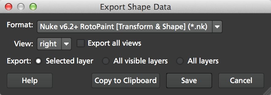
Nuke Roto exported as "Export All Views" will paste to Nuke as a combined roto node. If you would prefer the nodes to be separate, export using the different views instead of checking the all views option.
Exporting Rendered Clips (Mocha Pro)
You can export a clip to an image sequence or QuickTime format by choosing "Export Rendered Clip…" from the file menu.
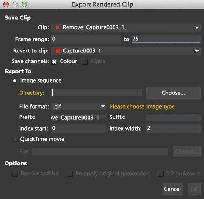
Options include:
Clip
Choose the clip you want to export.
Frame range
The range of frames you wish to export. If you choose to export the full range but have not rendered all your frames, the next drop down, "Revert to clip" will be used.
Revert to clip
Choose how to export frames that have not been rendered. If you choose None or the current clip to export, black frames will be exported for non-rendered frames.
Save channels
By default, this will just export the flattened render (Color), but if your render has alpha you can choose this also.
Export to
The export options for Image Sequences and QuickTime movies.
For Image Sequence you have the following options:
Directory: The directory where you want to export your image sequence.
File Format: A list of available image formats to render to.
Prefix: The name of the clip to go in front of the frame numbers.
Suffix: The name of the clip to go after the frame numbers (blank by default).
Index Start: The number to start the exported sequence from. By default this is the first frame in the timeline.
Index Width: The number of padding zeroes to use.
Exporting QuickTime movies
Which video file format reader you are using will determine the export handling of clips:
Using QuickTime: Choosing 'QuickTime movie' will bring up the legacy QuickTime export options when you click OK.
Using GStreamer: Choosing 'QuickTime movie' will bring up the GStreamer export dialog when you click OK. This currently only supports ProRes.

See the Video Files in Preferences chapter for more on clip exports.
Exporting Stereo Rendered Clips
The render dialog also allows you to render to single streams or a combined stream via EXR.
Go to File | Export Rendered Clips…
Choose the clip you want to export in the top drop down. By default it chooses the last render.
Select your frame range you want to export. This defaults to the In/Out range.
Under "Export Views" select the render option you want:
Current Only: Renders the current view you have selected.
To single stream: Renders all views to a single file. You are limited to rendering to EXR or SXR.
To separate footage streams: Renders the views as individual sequences.
Then choose your file path and render format.

If you have chosen to render the current view or separate footage streams, the view abbreviation will be suffixed to the rendered export automatically, so there is no need to define this in the file name.
The Camera Solve Module
| This section covers all Camera Solve features that are in Mocha Pro. Mocha HitFilm users do not have access to this version. See Mocha User Guides in HitFilm for more details. |
Overview
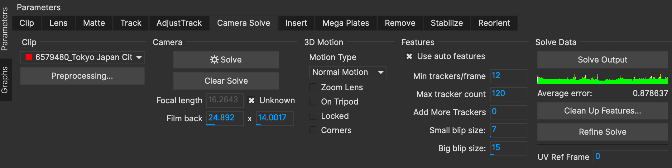
The Camera Solve module integrates Mocha Planar and PowerMesh tracking with Boris FX SynthEyes to solve cameras in 3D.
PowerMeshes and Planar Surfaces used to help the solve will be converted to textured meshes in the 3D scene.
Results and adjustments can be navigated via the 3D Viewer.
Camera Solve Limitations Camera Solves will solve only the rigid objects. |
The Camera Solve Workflow
Camera Solves work by tracking the scene and then determining a camera based on the relative movement of features within the scene.
While a lot of this is automatic, difficult or obscure shots will require some extra work to make sure your scene is interpreted correctly.
A general workflow of Camera Solving in Mocha is as follows:
Track any parts of the footage you want to get accurate placement using the planar tracker (Optional)
Track any parts of the footage you want to have static meshes using the PowerMesh tracking (Optional)
Mask any part of the footage that may interfere with the track (Optional)
Define the properties of the camera
Define how many auto features you also want to track with
Press the solve button
Adjust the resulting solve in the 3D Viewer
Export the results
Step 0 - Just try solving!
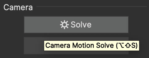
Unless you’re absolutely sure you’re dealing with a very long or complex shot or dealing with moving objects, the best starting point for any solve is to just click the Solve button and see what happens!
The default settings will give you a good grounding in the shot.
Step 1 - Mask any object that may cause a problem
If there are any obstructions in the shot that may cause a problem, you can first mask them out.
Usually this doesn’t have to be very accurate, it just has to generally cover the objects you don’t want to add to the solving process.
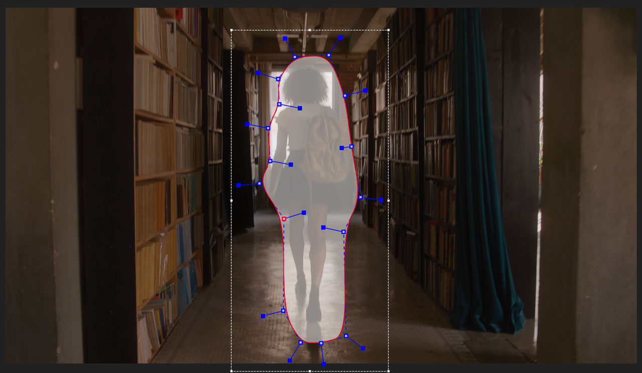
Good examples of items to mask will be:
Any moving object that takes up a significant portion of the shot. Things like actors that fill a large part of the frame or cars moving through the shot are good examples of this.
Any clusters of smaller moving objects that are high contrast that move through the shot or hang around for the entire shot
Very far areas like clouds or skylines that don’t contribute much to the overall scene
Often you may not need a mask as the solver is very good at discarding what it considers bad data, but if you’re not getting a good solve, masking is a good place to start.
Inverting the mask
Sometimes having to mask all the things that you don’t want to have in the solve can be tedious, especially if there is a lot of sky or water in your shot.
To avoid this, simply mask the area you actually want to have in the solve, then Invert the matte in Layer properties using the Invert checkbox next to Blend Mode.
Step 2 - Track anything in the shot where you want focused data
You can use Mocha planar tracking anywhere you think will help solve or place items in the shot.
Again, this is not absolutely necessary, but a good solid Mocha track can really help out in tougher shots, especially for moving objects.
Any solved planar surfaces will be converted into textured 3D planes in the viewport.
PowerMesh Tracking
You can also add PowerMesh tracking data for non-planar areas. Solving a shot that contains PowerMesh tracking will attempt to convert the tracking
into a textured 3D Mesh. This is exportable to Alembic, FBX and USD.
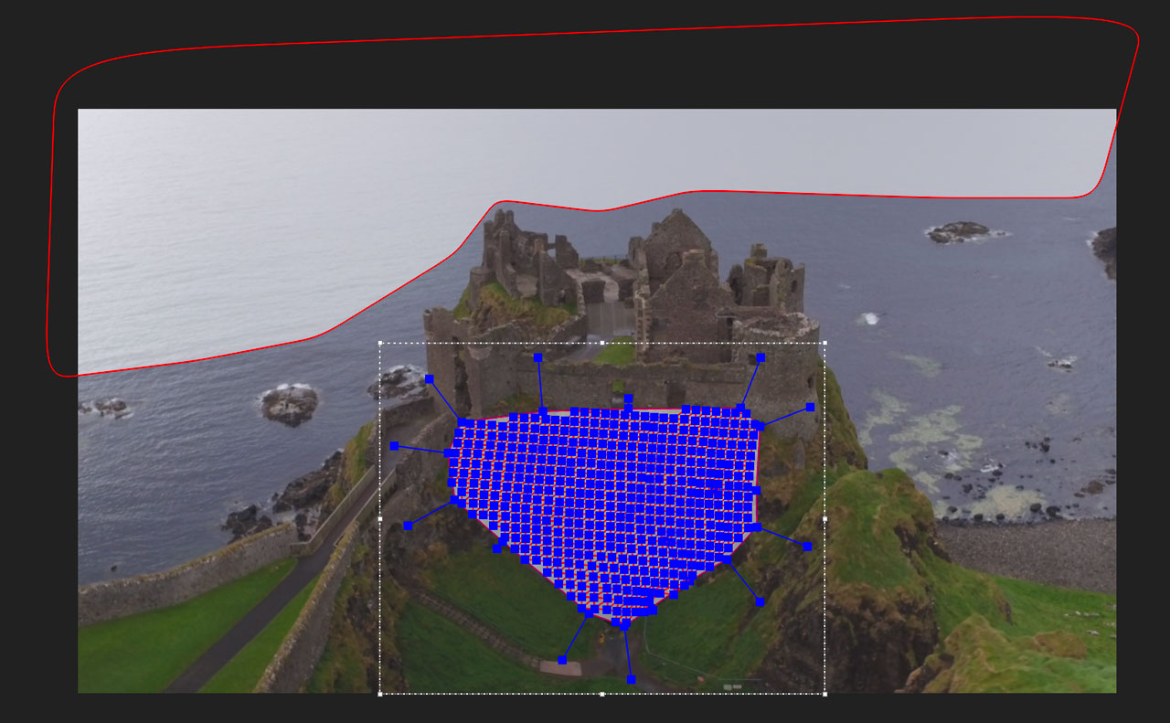
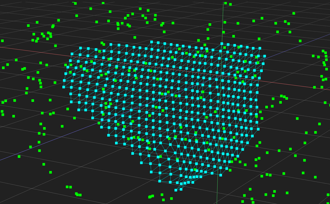
Step 3 - Set Camera Solve Parameters
At this point you can switch to the Camera Solve module.
Aside from the general clip properties, a 3D Camera solve requires some additional information to be as accurate as possible.
See the Camera Solve Parameters section below for detailed explanations of each of these parameters.
You also need to define what you want each 2D layer in your project to do.
In the layer controls in Camera Solve, there are 7 columns:

Visibility: This controls the visibility of the layer like any other
Processing Cog: Any layer with a Processing Cog icon will add that layer’s tracking data to the solve process. If you don’t want to use a layer in the solve, click the cog icon to turn this off.
Masking: The masking toggle. If you want a layer to mask any areas during the 3D solve, click this icon.
Moving Object: Select this for moving object tracks in the scene. See Moving Objects for more details on the best way to set up moving objects.
Lock: The standard lock toggle
Spline Color: The standard spline color swatch
Matte Color: The standard matte color swatch.
| Clicking a camera solve icon in layer controls will toggle the other icon off. You can’t process and mask with the same layer. |
Step 4 - Solve!
Once you have defined your parameters you can now click the Solve button.
The solver has 3 main processes which you will see in the progress bar in the top right corner:
Blipping: If you have auto features applied, the solver will go through the shot looking for features, or "blips", ignoring any area you’ve set as masked
Peeling: The solver will attempt to make trackers from the blipped features
Solving: The solver will take the auto features and the data from Mocha and attempt to solve the shot and generate a camera.
Depending on the length of the shot and how many trackers are defined, the solving part of the process will usually take the longest.
If you’ve been waiting a long time during solving, you can review what the solver is up to by clicking the Solve Output button.
Once the solve has finished, the 3D view will appear, looking through the solved camera and showing the features along with a ground plane grid.
If you have chosen to track a Surface or PowerMesh it will also be in the scene as a textured 3D mesh, but it is represented as individual vertices in the 3D Objects panel.
A graph will also appear in the Solve Data column, showing you the average pixel error for the whole scene.
The focal length field will also update based on what the solver calculated.
| A pixel error average below 1.0 is usually considered a good solve. If you have anything above 1.5 you may want to consider adjusting your parameters. |
Step 5 - Adjust
Once you have solved the shot you can make adjustments to review the scene.
On the right hand side is the 3D Objects panel containing a list of all objects in the solved shot.
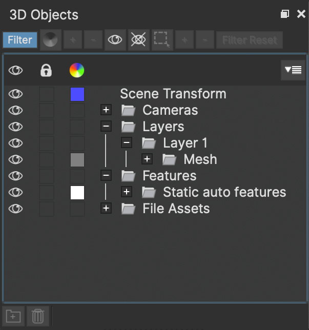
And the 3D Object Properties panel.

You can consider these like the 3D equivalents of the Layer controls and Layer Properties panels.
Selecting any feature will tell you its position in space. By default every feature has a rotation of zero and a scale of 1.
The Scene Transform
At the top of the 3D objects panel you will see an object called Scene Transform. This object is a parent of the entire scene and manipulating it will transform all features and the camera.
This is very useful for quickly adjusting the position, rotation and scale of a scene without affecting the solved camera or projection.
When you click Make origin or Align to Ground (see below) you are manipulating the scene transform.
Make Origin
The Make Origin button is used to center the entire scene, including the camera, around that point. The feature selected will be at the origin (0,0,0).
This will also set the Scene Transform pivot to the origin to make it easier to rotate around the axis.
Aside from the ground plane grid leaping to this point, you shouldn’t see any other change when looking through the Camera.
Align to Ground
When three or more features are selected, the Align to ground button will become active.
This rotates the entire scene to fit the selected points to the ground plane. At least 3 points are needed to make sure the angle of the rotation is adjusted across all axis points.
| It’s worth checking the different 3D views to see if your selected points are actually on the ground! |
Object Projection
As it can be sometimes tricky to detect exactly where a moving object is relative to the scene, the object might be not in the right place on solve.
This tool helps you rescale the moving object, which repositions it in space so it still looks correct in camera.
Step 6 - Refine
Once a solve has been completed, the pixel error graph may show red spikes or problem areas, resulting in a higher error than you want.
To help this, Mocha provides a Clean Up Features tool to allow you to disable or remove problem areas of the solve.
After Cleaning, you can click Refine Solve to take the existing scene and tidy it up further, readjusting the camera.
Step 7 - Export
Once you are happy with the scene, you can export your shot to your preferred package. See Exporting Camera Solves for more details.
Camera Solve Parameters
This section describes each parameter in the Camera Solve module parameters.
Like all Mocha modules, workflow for the Camera Solve is left to right.
Clip
The section focuses on the clip you’re currently tracking and preprocessing operations you can do to the frame images.
The preprocessing dialog is useful if your solve footage is low contrast or you want to enhance specific details.
The two items in the clip column are:
Clip: The current clip you’re tracking.
Preprocessing…: This button opens the preprocessing dialog that allows you to change the image’s contrast, gamma etc before you solve the shot. This is a separate processing to the tracking.
| For more information on the preprocessing dialog see the Preprocessing section in the Tracking chapter. |
Camera
This column covers the main solving buttons and the details of the physical camera.
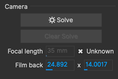
Solve: This button starts the solve process based on the settings you have chosen in parameters. Solving again will clear the previous solve.
Clear Solve: If you have created a solved scene, you can use this button to clear the solved data.
Focal Length: A field for entering the known focal length. "Unknown" is checked by default and will disable the field. This field is updated to the solved focal length after solving.
Film back: The horizontal and vertical film back of the camera, sometimes also known as sensor size. The fields will alter each other to match the dimensions of the clip if you modify a value.
3D Motion
This column defines the type of motion in the scene. Most of these options are based on the SynthEyes equivalent.

Motion Type: This dropdown has options for different types of camera motion:
Normal Motion: The most common type of camera motion. In most cases you will start with this.
Crash Pan: Used for very fast panning shots
Low Detail: For shots with very little trackable detail, such as green screen backgrounds.
Zoom Lens: If the camera is using any lens zoom during the shot
On Tripod: If the camera is mounted to a stationary tripod. This is used to solve PTZ shots
Locked: If the Camera is not moving at all. This is generally used to help solve for moving objects with no camera movement.
Corners: If there are any structural corners in the scene (buildings, windows, bricks etc). This can be helpful for solving scenes in non-organic environments.
Features
This column defines the auto features to track alongside any tracks you have made with layers.
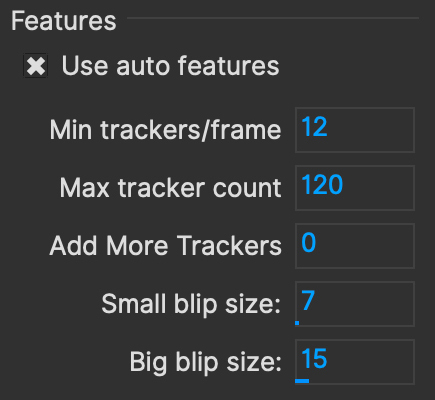
Use auto features: This will tell Mocha to use additional tracking features in the shot. If this is off, it will only use planar tracks and PowerMesh tracks.
Min tracker/frame: How many auto feature trackers to try looking for in each frame of the shot
Max tracker count: The maximum number of auto feature trackers to use in the entire frame range
Add More Trackers: Numerical field to add more trackers between the paths of existing trackers, to increase the density of the point cloud.
Small blip size: The smallest size of features to look for in the shot (in pixels)
Big blip size: The largest size of features to look for in the shot (in pixels)
Solve Data
This section displays solve results and options for exporting data.

Solve Output: This button opens a dialog that displays messages from the SynthEyes process. This output is useful for debugging problems in your solve.
Average Error: The HPIX graph or "Average Error" of the entire scene. This graph shows the average error on each frame, and the overall scene error. See "Average Error" below for more details.
Clean Up Features: This button opens a new dialog to help clean up the solve. See the Clean Up Features section below for more details on the options.
Refine Solve: This button lets you resolve with the existing data without having to solve from scratch. It’s recommended to use this after you have used the
Clean Up Featurestools. This button becomes enabled after you have completed a solve.UV Ref Frame: The Reference frame for UV coordinates. See more details below.
Export Camera Data…: Opens the dialog to export camera data. See Exporting Camera Solves for more details.
Clean Up Features
The Clean Up Features options provide options to remove problem features in the shot. Clicking OK runs through the options that have been selected.
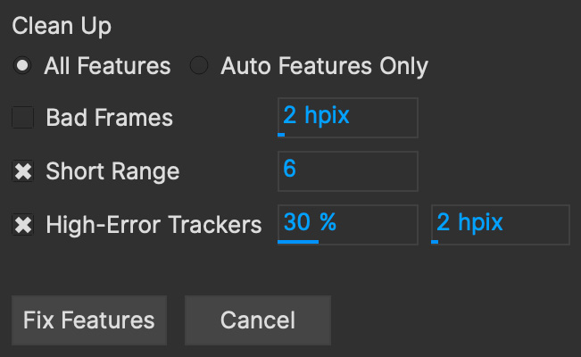
The Clean Up dialog has the following options:
All Features: The default is to clean all the features in the solve, including the ones using Mocha planar or PowerMesh tracks
Auto Features Only: Choose this option if you want to keep the manually tracked solve data intact and only clean the auto feature data
Bad Frames: This goes through the solve and looks for any frames that have an error higher than the threshold set in the field and disables them.
Short Range: Data that is only tracked for a short range of time can be unhelpful in the solve. This option will remove any features that are solved against a short-range of tracked motion as defined by the frames field.
High-Error Trackers: Similar to
Bad Frames, this option removes features if a certain percentage (the first field) of the feature has bad frames OR the average error is above the defined threshold in the second field.
We recommend using Refine Solve after cleaning.
UV Ref Frame
The UV Reference frame field lets you define the planar UV texture reference frame when previewing textures in the view and exporting mesh faces.
For example, if you plan to re-project your source image to the mesh on a certain frame, you can define it here.
By default this will be the frame on which you created the mesh or last adjusted the surface.
Features? Blips? Trackers? What are you talking about?
The 3D camera solver utilizes SynthEyes tracking and solving processes. As such, we use SynthEyes terminology to describe certain functions.
| For more in-depth details about tracking and solving workflow in SynthEyes, we recommend reading the SynthEyes manual. |
Features
This is a broad term to describe individual 2D (x,y) points of interest tracked in the scene. It can also be its 3D (x,y,z) equivalent after solving.
A feature can be:
A corner of a Mocha planar surface
A vertex in a PowerMesh
A single auto tracker or point created by the solver
Blips
A blip is a SynthEyes term for a single point of interest in one frame.
When the SynthEyes process creates auto features, the first phase is to look at every frame and create blips by looking for interesting features and labeling them.
Inside Mocha, this is an invisible process and just part of the camera solve, but you can refine the size of the blips to look for in the parameters.
Trackers
In Mocha, tracking is a frame-to-frame process searching for patterns that move in the same direction over time.
For auto features in SynthEyes, tracking is generated by identifying blips over time that correlate with each other and turning them into feature trackers.
This process is called "peeling" and you will see this term in the progress bar when the camera is solving.
More trackers
The Add More Trackers field is a way to add more density between existing trackers.
This works by looking at the trails of existing auto features and placing more features along those paths.
While this is usually a good way to add more points to your solve, keep in mind that the more trackers you add, the longer a solve will take to refine.
Average Error - The Solve Quality
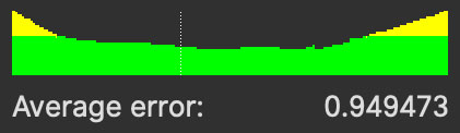
When a solve is complete, a graph under Solve Data will appear.
This is the Horizontal Pixel Error or (HPIX) graph, and represents the average pixel error in the scene along with indicators for every frame.
What is Horizontal Pixel Error (HPIX)
Horizontal Pixel Error is a measurement of the distance between:
The 2D position of a solved 3D (XYZ) feature, projected into the image
The actual 2D position in the image from the original tracked point
For example, if you have a corner of a planar tracked surface locked firmly to the corner of a wall and the solved 3D point for that corner varies at all, the horizontal pixel error is the difference between the 2D point and the 3D point.
The Average Error, listed under the graph is an average of all features for all frames in the shot.
Good vs Bad Error
In general you should be aiming for an average error below 1 pixel. An error of 1-2 pixels isn’t terrible, but 0.9 or below is excellent.
In short, the bigger the error is, the worse the solution is.
For very high error features, Mocha will automatically remove the point during clean up.
In some cases, Mocha will say it could not solve the shot. This is normally because the pixel error was so high that all features were removed and a good solve could not be reached.
If this occurs, we recommend either manually tracking a few areas with the planar or PowerMesh tracker or adjusting the number of auto features and blipping sizes.
Solving 3D Moving Objects
| Currently Mocha Pro can only solve one moving object per scene but a single solve can comprise of multiple tracked layers. See the section on clustering layers in groups below. |
Mocha can solve for a moving object in scene as well as the camera.
Moving objects can be tricky to solve in a 3D scene so there are several approaches you can take to make sure you get a good result.
Track with a PowerMesh
PowerMesh is great for getting multiple dimensions of a moving object in a single layer. This is especially helpful for rounded or rough objects that don’t have distinct planes.
For example, in the image below we have tracked a basket using the PowerMesh for the front and side:
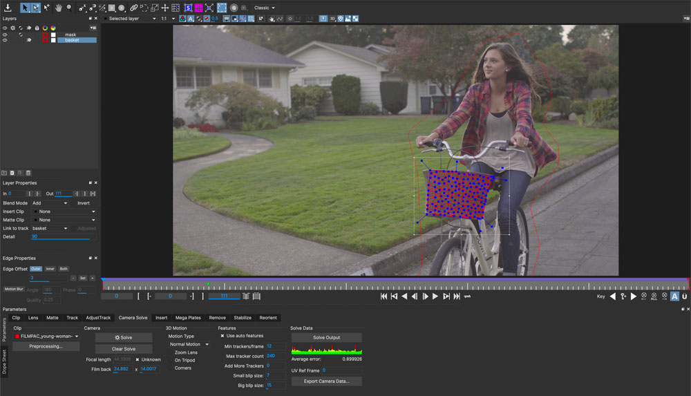
When solving, if the PowerMesh is tagged as a Moving Object in the layer controls, it solves as a moving 3D mesh:

| Like with camera solving, Moving Objects cannot be solved with deforming Meshes. Only track rigid objects. |
Cluster layers in groups
If you cannot get a good PowerMesh track or you need more information, the best way to get good results is to use separate layers and group them. A grouped set of layers is assumed to be part of the same moving object.
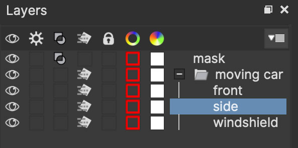
| Since grouping is assumed to be part of the same object, avoid grouping different types of solve objects under the same group. |
Track as many sides of the object as you can with different layers. For example, the top, side and front. Two sides will often be enough but the more the better.
Partial tracks will also help the solve as long as you can cover the entire timeline with multiple tracks. For example, if you have a shot of a car moving down a track,
you can track one side of the car and stop the track before you lose it on the turn. You can then track the front and windscreen of the car and group all three layers together, like so:

When solving, the layers inside the group should all be moving objects. Also tag the group itself as a moving object. If the moving object toggle is off, it won’t solve.

If you have enough data from all 3 tracks, you should still get a solve for the entire set of points.
Solving Moving Objects with a Locked Camera
If you have a locked shot where the camera is completely stationary, you can still track moving objects in the scene and solve for them instead.
Track and set up your moving objects as normal (see above)
Check "Locked" in the 3D Motion parameters
Solve
This will produce a 3D locked camera and the moving 3D object.
Try Moving Masks
If you don’t think you have enough data to track the object with Mocha layers, you can hand-keyframe a mask around the object or use Matte Assist ML masks to cover the object.
This will leave it up to the solver to automatically find points, similar to the Auto features used in the scene solve.
If you want to try this approach, it’s important that you don’t track the mask because that tells Mocha you want to use the tracking data in the layer instead.
Object Projection
When you solve a moving object it will look like it is moving correctly in camera, but occasionally will not be sitting in the right place in space.
This is usually because it has been difficult to project how far back in the scene the object is.
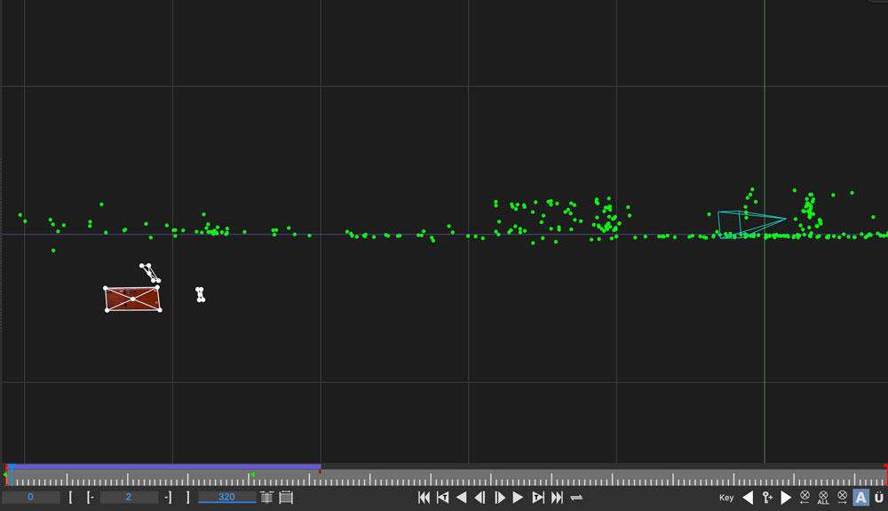
To fix this, you can use the "Object Projection" controller in the Align panel to adjust the position relative to the camera.

To adjust the moving object:
Select the moving object parent group in the 3D Objects panel:
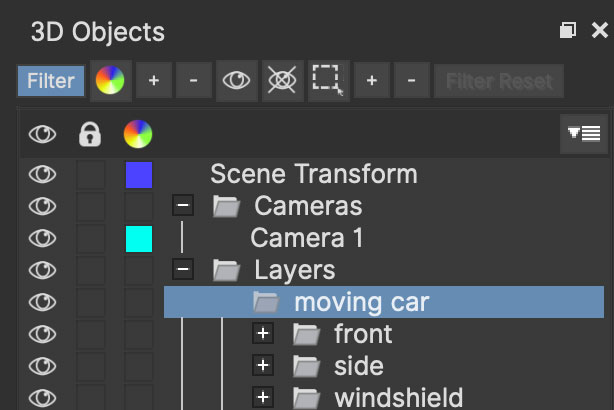
Switch to a view where it is easy to see the misplaced object. We recommend the Left view as often you will be dealing an object below the ground plane
Adjust the
Object Projectionfield in the Align panel. Negative numbers bring the object closer to the camera and scale it down, and positive numbers push the object further away and scale it up. You will usually be scaling down
The Object Projection field will always bounce back to 100% as this is not a relative alignment. You can keep adjusting until you have the moving object where you want it in the scene.
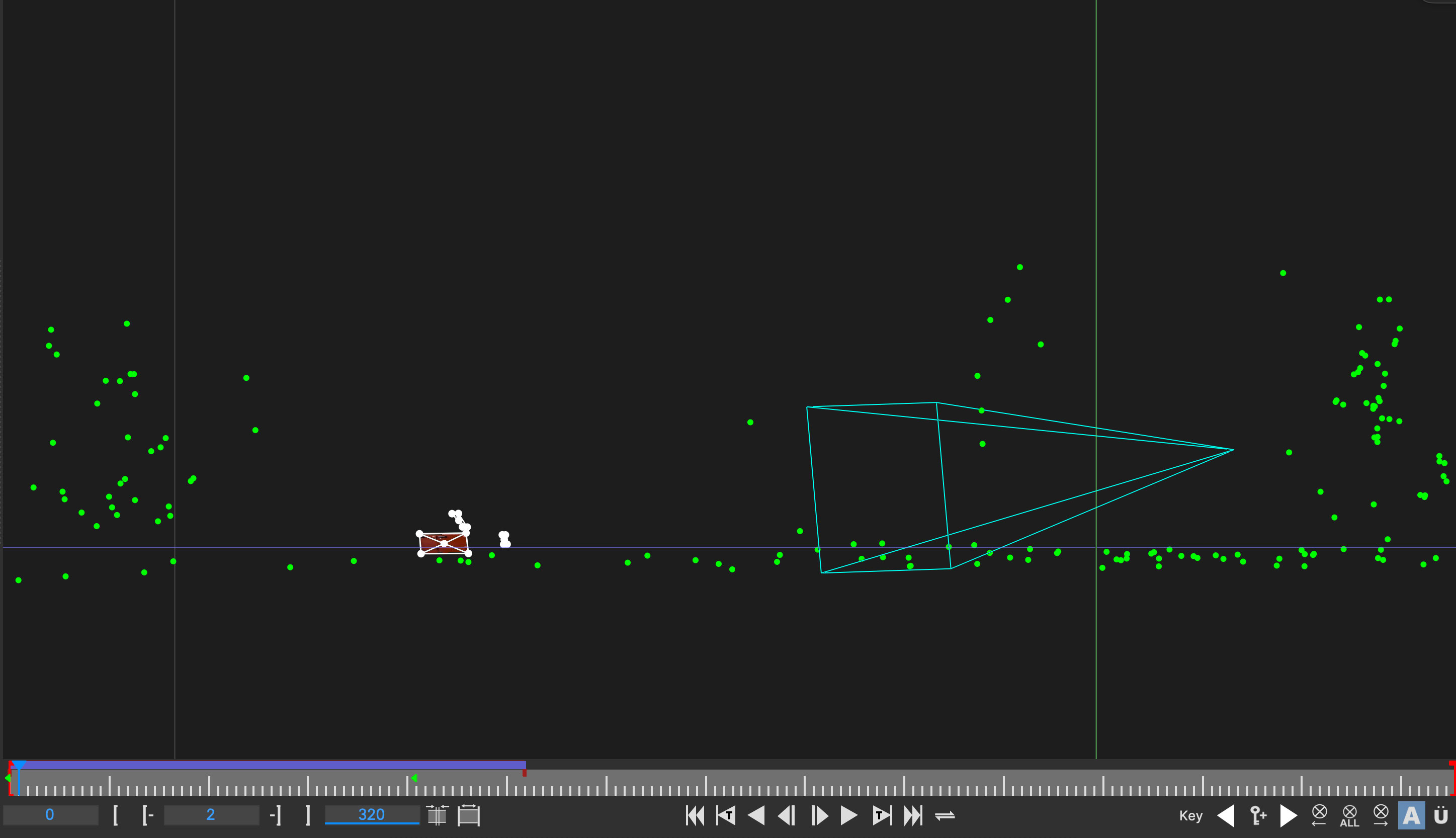
Navigating the 3D Viewer
When you have completed a solve, the Camera Solve module will switch into the Camera Solve layout and turn on the 3D view mode.
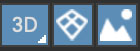
The main 3D view controls are (left to right):
3D: The toggle button for turning on the 3D viewer. When off, MOcha will show the standard 2D view. Pressing and holding this button lets you select the view (see below)
3D Ground Plane: The 3D grid that represents the ground plane. This turns on by default when you first perform a solve.
Background Footage: Toggle showing or hiding the background footage in the 3D Camera view.
If you press and hold the 3D button you are presented with different views:
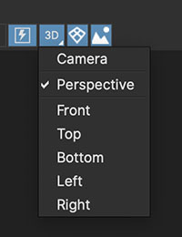
Camera (default): This view looks through the solved camera and displays a projection of the footage so you can easily see results
Perspective: This is a free-moving perspective mode so you can navigate around the scene
Orthogonal Views: Front, Back, Left, Right, Bottom and Top views show orthogonal views of the scene for lining up your ground plane or preview models.
Mouse navigation
While in Perspective view, you can move about the scene using standard camera shortcuts:
Alt + Left Mouse Buttondragging will rotate the viewAlt + Middle Mouse Buttondragging will pan the viewAlt + Right Mouse Buttondragging will dolly the viewMiddle Scroll Wheelwill also dolly the view in and out
In the orthogonal views only Pan and Zoom will work. You cannot rotate them.
If you use the rotate shortcut while in Camera view, it will switch to Perspective view.
Resetting 3D views
After working with the 3D viewer for a while, you may want to restore the views back to a default position.
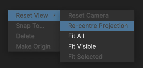
You can right click any view and select options to set the camera:
Reset Camera: Resets the camera back to its default position for that view.
Re-center Projection: This places the solved scene back to the center of the viewer to make it easier to preview the shot
Fit All: Fits all solved objects into the view, including the camera. This is especially useful in the orthogonal views.
Fit All: Fits all visible objects into the view, including the camera
Fit Selected: Fits Fits all selected objects into the view
3D Objects and Properties
Once a scene is solved, the 3D Objects list will appear by default on the right.
Scene Transform: The parent transform for the entire scene. Rotating, moving or scaling the scene transform will apply those changes to the whole scene non destructively.
Cameras: This folder contains the cameras for the scene.
Layers: Any features that 2D Mocha layers contributed to the scene, including planar tracks and PowerMesh tracks solved into 3D points or meshes
Features: Auto features generated by the SynthEyes solve process.
File Assets: Imported models. See Importing Models below.
You can hide, lock or change the color of any selected object in the 3D objects list.
Underneath 3D Objects will be the 3D Object Properties. Clicking on any object in the 3D Objects list will highlight the properties for that object:
Position: View or change the X, Y or Z position of an object
Rotation: View or change the X, Y or Z rotation of an object
Scale: Read or change the X, Y or Z scale of an object
Uniform Scale: While this box is checked, changing any scale field will change the value for all scale fields.
Reset: Reset the scene transform.
Source: Change the source model for the selected File Asset. See Importing Models below.
Filtering the 3D Object Panel
Since you can end up with hundreds, if not thousands of objects in the 3D Object panel, you can filter the panel to reduce congestion.
Note that this is specifically for filtering the panel for object management. It doesn’t filter what is in the viewport.

Along the top of the panel you will see several icons next to a Filter button. Hover over each to see the tooltip of what they do:
Filter: Toggle the filter on or off.
Filter Colors: Use this to add specific colored features to the filter. Those not included in the color filter will be hidden in the 3D Object Panel
Add/Remove Colors: The + and - symbols next to the color filter button allow you to add or remove the specific color from the filter
Filter Visible: Use this to add visible features to the filter
Filter Non-visible: Use this to add non-visible features to the filter
Filter Selected: Use this to add selected features to the filter. This is very useful when wanting to isolate what you’re working on in the viewport
Reset Filter: Clear the filter but keep it on.
You can also filter by using the right-click menu in the Viewport, which makes it much easier to narrow down what you’re working with in the 3D view.
Additionally, there are shortcuts in the right-click menus to hide the selected or unselected objects.
Selecting
To select objects or features, either left-click drag to select a bunch of objects or click individual items and
hold the Shift key while clicking to add to the selection.
You can invert a selection by right-clicking in the 3D object panel or the 3D Viewer and choosing "Invert selection".
Collapsing and Expanding the 3D Object panel features
As you’re dealing with a lot of trees of information, you can also quickly collapse or expand portions of the hierarchy.
If you right-click the 3D Object panel you get a bunch of additional menu options.
Right down the bottom of the menu you have two sub menus:
Collapse
Expand

You can choose to collapse/expand all items in the panel, or just the tree the selected item is underneath. This makes it much easier to see and work with the whole structure.
3D Alignment
Underneath 3D Object Properties is the Align panel:
This lets you manipulate the scene to line up with the ground or objects.
Make Origin: Selecting any single feature and clicking this button will position the whole scene to this point and make it the center of the scene (0,0,0).
This will also make the pivot of the Scene Transform position to this point to make it easier to rotate.
Selecting more than one feature will disable the button.Align to Ground: Selecting 3 or more points and clicking this button will attempt to rotate the entire scene to align to the ground plane based on your selection.
You need at least 3 points for this to work to ensure alignment occurs on each rotation axis.Reset: This resets any alignment.
Snap To: This is for aligning the position of imported models to features in the scene.
To snap a model, select it in the viewer or 3D objects and clickSnap to…then select the destination feature in the scene.
Object Projection: This lets you reposition and scale a moving object without changing its position in camera. Select the moving object folder in the 3D object panel to use this tool.
Importing Models
| Mocha currently does not support animated USD geometry |
You can import USD 3D models into Mocha via the file menu.
Go to File > Import > USD 3D Object… and select your model from the file browser.
The model will then appear in the 3D Viewer and be listed under "File Assets" at the bottom of the 3D Objects panel.
You will most likely need to scale and rotate the model after import as every package is different.
Snap Imported models to Features
To make positioning easier, you immediately move your model to an existing solved feature using the Snap to.. button in the Align panel.
Select your USD model in the scene
Click the
Snap to…buttonClick a feature in the 3D view.
The model should then reposition to the point selected.
If the target is a 3D moving object, the imported model will be parented to that object.
You can remove this link by selecting the imported model and clicking Detatch parent.
Exporting Model Placement
When it comes time to export your 3D scene, Mocha will also export a null with the imported model transform so you can easily line up the model in your target application.
If you export to SynthEyes or Alembic, Mocha will also export the model itself.
Measuring Distance
To give a sense of scale, there is also the Measure Distance tool in the toolbar:

Clicking the measuring tape icon reveals a Distance field.

This field only becomes active when you select two points in the solved scene.
The process for getting the distance is:
Select the
Measure Distancetool (tape)Select 2 points in your scene that you know (or estimate) the distance between
In the active Distance field next to the Measure tool, enter the known or estimated value.
Entering the value, you should see no difference in the scene. This tool is simply setting a scale for the whole scene based on your selected measurement.
You can see this if you select any other two points. They will now be scaled in the distance field relative to your original measurement.
The measured distance setting will be applied to your export to more easily match up with your unit scale.
Estimating Distance Tips
If you’re not entirely sure what the correct distances are, your best bet is using markers in your scene that would be a standard size.
For example, the width of roads, doors or windows in countries are usually a standard size.
You can also use the approximate height of a person in the scene to get a rough estimate.
Exporting Camera Solves
| Importing Mocha Pro 3D camera solve data into After Effects requires the Mocha Pro Adobe plugin or the "Mocha 3D Track Importer". Go to https://borisfx.com/downloads to get the plugin. |
Supported formats for export are:
Universal Scene Description (USD)
FilmBox (FBX)
Alembic (ABC)
After Effects 3D Motion Data
HitFilm Composite Shot (HFCS)
Boris FX SynthEyes Project (SNI)
Universal Scene Description (USD)
The USD format is being quickly adopted by many hosts as a standard for handling large sets of data.
Follow your target host’s import instructions for how to handle USD format correctly as each one handles it slightly differently and level of support varies.
FilmBox (FBX)
The FBX format is a useful animation transfer format for camera data.
Note in the export that we support 3 main types of FBX:
FBX 6.1.0 (for legacy support)
FBX 7.7.0
FBX 7.7.0 for Nuke
The reason for a separate Nuke format is that Nuke interprets FBX axis directions differently to other hosts.
We also use 7.7.0 specifically because we don’t need the additional properties in current FBX formats to export point and camera data.
Alembic (ABC)
The Alembic format is another useful 3D standard for Meshes camera data. It is based on the same export available in SynthEyes.
If you imported any models in the your Mocha 3D scene, these will also be exported with the Alembic file.
| This version of the Alembic format should not be confused with the Alembic exports in the Track module, which export 2D Meshes with warping instead of solved 3D data. |
After Effects 3D Motion Data
| If you are using the Mocha Pro Adobe Plugin, you can generate data directly from the plugin interface. See Generating 3D Camera Data for more details. |
This format utilises a custom After Effects plugin called the "Mocha 3D Track Importer" that allows you to paste Mocha camera solve data directly to an AE Comp. By default this is built into the Mocha Pro Adobe Plugin.
If you don’t have the Mocha Pro Adobe plugin installed, you can download the plugin from the Boris FX website here: https://borisfx.com/downloads
To access the data:
Install the plugin and start (or restart) After Effects
Inside the Mocha Camera Solve module, select the points you want to export with the camera
Click on
Export Camera Data…Select
After Effects 3D Motion Datafrom the dropdown in the Export Camera Data dialogCopy the data to the clipboard using the
Copy to ClipboardbuttonSwitch back to After Effects and in your Comp, go to
Edit > Paste Mocha camera
Pasting will then creates two sets of data:
The Camera
3D nulls based on the features in the solve
Creating nulls in After Effects can be a heavy process, so we recommend selecting the points you want to export first, then choosing Selected from the options before clicking Copy to Clipboard.
If you want all the points, expect to wait a little while After Effects generates the relative nulls.
HitFilm Composite Shot
While you can now import FBX into HitFilm, we still offer the ability to import the composite shots as well.
Exporting Camera Data Process
The basic procedure for export is:
Click Export Camera Data…
Choose the format you wish to use from the drop-down.
If you are exporting to After Effects, click Copy to Clipboard.
If you choose Alembic, FBX, USD or SynthEyes click Save and create a filename.
You can then paste into After Effects using the "Paste Mocha camera" option in the Edit menu, or import your USD, Alembic or FBX data into the program of your choice.
Export Options
Depending on the Export type, you will be presented with several options to choose from.
| Not all export formats support all options. |
Export feature points: Export the features as well as the camera. This is on by default
Export Mesh faces: Export solved PowerMeshes and Surfaces as face data instead of individual points. This is on by default
Bake scene transform: Bakes the top-level parent transform used to modify the entire scene into the individual points and camera. In After Effects exports, baking is done by default.
Export points
For FBX, Alembic and USD formats, this dropdown provides options for converting the features in the scene to different types:
Individual Meshes: Export each feature point as a small inverted pyramid, with the tip of the pyramid acting as the feature position.
This type is useful for easily seeing the points in the scene, especially if your host is not suited to displaying nulls.Nulls: This will export features as null objects with transform data.
Exporting to SynthEyes Projects
When exporting from the Export Camera Data dialog, you also have the option to export to Boris Fx SynthEyes (SNI) project files.
These files will contain the following information:
All 2D Planar Tracks and PowerMesh tracks used to solve the scene in Mocha
All 2D auto tracks generated by the SynthEyes solver
All 3D solve points and the camera from the final solve result.
Any imported models you brought into the Mocha 3D scene as linked models
The project files will not contain:
Any masks used to occlude objects in Mocha
Any adjustments to the 3D data done in Mocha after the initial solve.
Importing Mocha 3D Data to Compositors
This section covers various compositing hosts and how to import the 3D data.
We won’t cover major 3D packages below as you’ll find similar approaches across the board for Maya, Blender, Cinema 4D etc.
See the user guides for your destination application on importing USD, FBX and Alembic.
After Effects
Importing to After Effects can be done in several ways:
By using "Paste Mocha Camera" from the edit menu. This requires that the Mocha Pro Adobe plugin or the Mocha 3D Track Importer plugin is installed.
By generating the data directly via the Mocha Pro Adobe plugin interface. See Generating 3D Camera Data in the plugin section.
Paste Mocha Camera
When you export After Effects 3D Motion Data to the clipboard it will be recognised by the installed plugin and enable the "Paste Mocha Camera" menu item in the After Effects Edit menu.
You can then select this option and After Effects will generate:
A set of 3D nulls, depending on what you selected on export
An After Effects camera
There will be a lot of features when performing camera solves, so it’s recommended to only export what you need (using "selected" or "Visible" options in the exporter), as generating a lot of nulls can slow After Effects down.
Nuke
To import to Nuke, you need to export either USD, FBX or Alembic data.
| Importing is based on Nuke 14 and 15. Your experience may vary according to your version. |
Alembic Data
Import the file by pressing 'r' on your keyboard and loading the Alembic.
Nuke will automatically determine the type and display some information, then ask you if you want to create an all in one node.
Nuke will then generate a
ReadGeonode and aCameranode based on the file.Input the
Cameraand theReadGeointo a newScenenodeCreate a
ScanlineRendernode and feed theReadGeointo the obj/scn input, then theCameranode into the Cam inputFinally add the footage to the bg input
If you have exported the features as "Individual Meshes" you should see an array of tiny inverted pyramids in the view.
Nulls exported to Alembic are not currently supported in Nuke. Import FBX nulls instead, or use the Individual meshes option. |
USD Data
| At time of writing, some USD tools in Nuke are still in beta. |
Nuke currently has two ways of handling USD data:
The "3D Classic" way, using the same nodes as Alembic and FBX
The "3D" way which are nodes that handle USD scenegraphs specifically.
3D Classic
Import the file by pressing 'r' on your keyboard and loading the USD.
Nuke will automatically determine the type and display some information, then ask you if you want to create an all in one node.
Nuke will then generate a
ReadGeonode and aCameranode based on the file.Input the
Cameraand theReadGeointo a newScenenodeCreate a
ScanlineRendernode and feed theReadGeointo the obj/scn input, then theCameranode into the Cam inputFinally add the footage to the bg input and view.
3D
| The nodes listed below refer to the 3D menu specifically instead of the 3D Classic options. |
Import the USD file via a
GeoImportnodeCreate a
Cameranode and feed theGeoImportnode into the scene inputInside the
Cameraparameters, select "Import Scene Prim" and change the "Import From" dropdown to "Scene Input"Inside the
Cameraparameters, under the "Import Prim Path" select theMochaCamerain the scenegraphInput the
Cameraand theGeoImportinto a newGeoScenenodeCreate a
ScanlineRendernode and feed theGeoImportinto the obj/scn input, then theCameranode into the Cam inputFinally add the footage to the bg input and view.
If you’re finding it hard to see the individual points, you can feed the GeoImport node into a GeoPoints node and scale the Point Size.
FBX Data
| FBX utilizes the "Classic" 3D menu tools. |
Create a
ReadGeonode and load in the FBX via the file fieldCreate a
Cameranode and read in the FBX file in the Camera parametersInput the
Cameraand theReadGeointo a newScenenodeCreate a
ScanlineRendernode and feed theReadGeointo the obj/scn input, then theCameranode into the Cam inputFinally add the footage to the bg input
If you have exported the features as "Individual Meshes" you should see an array of tiny inverted pyramids in the view.
If you have exported Nulls you may need to choose "Point Cloud" from the "object type" dropdown in the ReadGeo parameters.
Fusion
Like Nuke, Fusion has different ways of handling imported 3D files. Fusion supports USD, FBX and Alembic in different ways.
| Importing instructions are based on Fusion 19, which supports turning off keyframe optimization. If you are using an earlier version, you may need to scale your scene to avoid Fusion removing keyframe from the import. |
Alembic Data
Alembic data is read in and converted to native Fusion nodes. Once imported, you need to set it up to be seen in the viewer.
| Importing Alembic files with a lot of features generates a large tree of nodes and may take a long time to generate in Fusion. Consider exporting only the features you need from Mocha. |
Go to the file menu and choose
Import>Alembic scene…Select your exported alembic file, which opens up the Alembic importer dialog
In the importer dialog, check to make sure the Animation "Resampling rate" is set to the frame rate of your footage
To avoid Fusion aggressively thresholding keyframes, turn off "Remove Duplicate Keyframes" (Note this option was introduced in Fusion 19)
When you’re happy with the other settings, click OK
Fusion will then generate a tree of feature points and meshes
(Optional) While all imported items are still selected, right-click and select
Groupor press Ctrl/CMD + G to group the itemsCreate a
Renderer3Dnode to the group to render the results
If you are using the "Individual meshes" export, you will get a node per feature. Keep this in mind if you have a lot of features!
Nulls exported to Alembic are not currently supported in Fusion. Import FBX nulls instead, or use the Individual meshes option. |
FBX Data
Go to the file menu and choose
Import>FBX scene…Select your exported FBX file, which opens up the FBX importer dialog
In the importer dialog, check to make sure the Animation "Resampling rate" is set to the frame rate of your footage
To avoid Fusion aggressively thresholding keyframes, turn off "Remove Duplicate Keyframes" (Note this option was introduced in Fusion 19)
When you’re happy with the other settings, click OK
Fusion will then generate a tree of feature points and meshes
(Optional) While all imported items are still selected, right-click and select
Groupor press Ctrl/CMD + G to group the itemsCreate a
Renderer3Dnode to the group to render the results
If you are exporting nulls, they will come in as a point cloud. You will need to make them renderable in the point cloud node to see them.
The Insert Module
Overview
| Some features in this section only relate to Mocha Pro. This feature is not available in Mocha HitFilm or Mocha AE. For a full comparison of features, please refer to the comparison chart online. |
The Insert module is where you choose the image you would like to insert into your tracked layer. You can import a still frame or a moving sequence. Once imported, the Insert module provides a comprehensive range of tools for matching this new image to the original background layer. The skill here, naturally, is to make the newly imported image look like it was in the original shot all along.
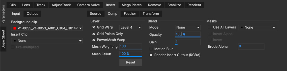
Input
This is where you choose the Input Clip or background layer and the Insert Clip or foreground layer, and optionally a separate input clip with an alpha channel for compositing.

Background Clip
By default Mocha Pro selects the last clip that was tracked as the input. If you want to change the input, just select a different clip from the pulldown menu.
Insert Clip
This clip mirrors the Insert Clip inside Layer properties, i.e. if you change one, the other also changes.
By default mocha Pro selects None as the foreground input, expecting you to make a choice of your own. To choose an insert select the Import button and use the file browser to locate a still frame or a file sequence that you would like to appear over the tracked background clip.
In the Mocha Pro Plugin, you can choose an 'Insert Layer' placeholder that reads from layers back in the host timeline to render in Mocha.
Pre-multiplied
Check this is you want to force the alpha in the insert clip to be pre-multiplied. Off means the clip remains straight alpha.
Output [Standalone only]
Here you can select the name of the clip to be output. Once a clip has been rendered it is automatically named Composite_<clipname>.
To choose a different name for the output clip select the New… button and choose a new name.
The remainder of the controls in the Insert module dictate both how much of the insert is displayed and how it is displayed during the course of the shot.
Source and Region of Interest (ROI)
This controls the area of the insert clip that you would like to be displayed in the tracked layer.
The source "Region of Interest" (ROI) can move anywhere on the insert image, including outside it.
As you adjust the ROI, the insert is scaled to fit the surface.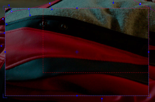
There is also a Reset button to reset the ROI to the corners of the insert image.
By default, the aspect ratio is locked. Uncheck Lock Aspect Ratio to allow arbitrary ROI changes.
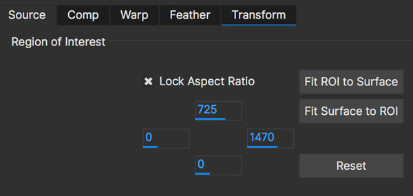
To adjust the ROI aspect ratio to match that of the background image given its current position and shape in the background image,
click on Fit ROI to Surface.
Conversely, the Fit Surface to ROI button moves the surface position to match the aspect ratio of the insert image, given its ROI settings.
These controls will work best if you are in a frame where the insert is as front-on as possible.
For them to work correctly, the pixel aspect ratio of both the input clip and insert clip must be correct.
A common issue is that if the resolution of either clip is not recognized when the clip was imported, it is assigned the PAL camera type.
This may not give the correct pixel aspect ratio. To check this, switch to the Clip module and select each clip in turn,
checking the appearance on the screen to make sure that each clip appears correct on the screen.
If not, change the Film Type. If you know that the pixel aspect ratio of the clip is one (square pixels)
select Custom as the Film Type and set the pixel aspect ratio to one.
The number fields are positioned in the menu to relate to the edge of the ROI that they adjust.
So, to reduce the height of the insert ROI at the top of the frame, decrease the value in the top ROI number field by
dragging or highlighting the current value and typing in a new value.
Similarly, to reduce the height of the insert ROI at the bottom of the frame, increase the value in the bottom number
field by dragging or highlighting the current value and typing in a new value.
The same applies for the left and right edges of the frame with the left and right number fields.
Comp

Layer
This section handles how to warp the Layer Insert Clip
Grid Warp
If you turn on "Grid Warp" in the warp tools you can use the a grid to distort the image inserted in the layer.
The dropdown can set the level of detail in the grid. There are 4 levels, with Level 1 being the lowest detail.
Below is an example of Grid Warp set to Level 2:
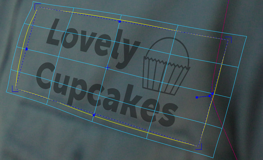
You can warp the grid points in the viewer to adjust your insert, or use the outer yellow lines to bulge or pinch the edges.
Grid Points Only
This shows only the intersections of the grid lines instead of the lines. This can be useful when you need to see the underlying insert image while adjusting the warp.
PowerMesh Warp
This checkbox activates the controls so the grid warp can be weighted and distorted organically by the PowerMesh.
When this option is off, the grid warp only follows the planar motion of the track.
| You need to have tracked a PowerMesh before this option will have any effect. See PowerMesh and Mesh Tracking for more details. |
Mesh Weighting
This controls how much the Grid Warp is distorted by the PowerMesh. At 100% weighting, the PowerMesh warps the grid at full strength. At 0% the grid only follows the planar surface.
Mesh Falloff
This controls how much the Grid Warp is affected when overlapping the edges of the PowerMesh. If the Grid is outside the PowerMesh area, it will still be influenced if the falloff is above zero.
In the example below, the grid point is being warped too far by the PowerMesh:

Adjusting the PowerMesh falloff to 0% tells Mocha to ignore the grid outside the mesh boundaries, and pulls it back into place:

Reset
This button resets the Grid Warp back to the original unmodified grid and changes the PowerMesh warp settings back to the defaults.
Blend
Mode
This dropdown sets the blend mode. Options include:
Darken
Multiply
Color Burn
Lighten
Screen
Color Dodge
Overlay
Softlight
Hardlight
Color
Luminosity
Difference
Opacity
This parameter controls the opacity of the foreground image insert. It is a multiplier of the alpha of the insert, applied before the composite.
Gain
This is where you color correct the insert once it has been added to the tracked layer.
Motion Blur
Select this button if you want to apply motion blur to your insert.
Render Insert Cutout (RGBA)
This renders the cut out of the insert with alpha along with the composite file. Turn off if you only want the composite render of the insert.
Masks
Use All Layers
If you want to mask off an area of your insert, clicking on this tool will cause the rendered
insert to only change the pixels within the mattes above and including the current layer.
If the checkbox is switched off, you can select an individual matte to use instead.
Invert
Inverts the mattes of the Insert.
Invert Alpha
Inverts the Insert Alpha if it exists.
Erode Alpha
Change this value from its default zero value to erode the alpha channel of the insert by the given number of pixels.
Feather
If you want to add a soft edge around the edges of the insert, use the Feather controls. There are separate controls for the left, right, top and bottom edge widths, which are between 0 and 1, where the value 0 indicates no edge and 1 means that the edge covers the whole of the insert.
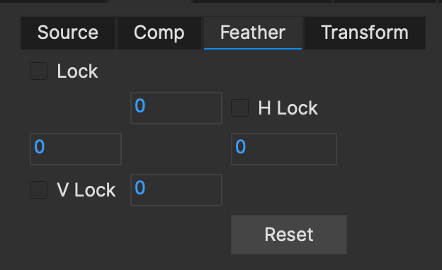
If you switch on Lock, all four edges are locked to the same edge width. H Lock and V Lock apply lock separately to the left/right and the top/bottom edges respectively.
Transform
This section controls a level of corner pin control on top of the adjusted track. This feature is particularly useful for curved surfaces. It allows the corners of the surface to be used in the same way as the warp control points (described below) – by aligning the newly imported insert with a region of the tracked image independently of the blue surface contour, which follows the adjusted track.
The offset region is drawn in yellow underneath the existing blue surface. You can use the new points either by dragging the sliders to increase or decrease the value of the coordinates, or by highlighting the numeric field and typing in a new value. In addition to this you can hold down the Alt and Control keys on the keyboard (Alt+Cmd on a Mac) whilst dragging a surface point or line to achieve the same result. The new points created are offset in a controlled way from the adjusted track.
Hold down Alt, Control and Shift (Alt+Shift+Cmd on a Mac) to gear the changes down 10 times. There is finally a Reset button to return the offset parameters to their defaults.

When using the rotate tool to rotate the offset surface, the pixel aspect ratio of the insert clip will be used to create the correct effect. If it is not correct the offset surface will appear to squeeze or stretch as it is rotated. See the ROI section to see how to fix this problem.
Export Offset Tracking Data [Mocha Pro]
Export the transformed track. The offsets are keyframed settings of the position of the insert.
Inserting in Stereo
All inserts are warped in stereo if you have tracked both views.
You can render the insert for both views by selecting Operate on All Views button next to the Render buttons on the timeline.

Rendering the Insert in the Plugin
You have a lot of control over the Insert renders in the plugin interface.
See Rendering Insert Layers in the Mocha Pro Plugin section of the User Guide.
Insert Render Resampling
If you want to change the type of resampling applied to an Insert render, you can change this in the Project Settings.
Go to `File > Project Settings…`and look for the "Resampling" section:
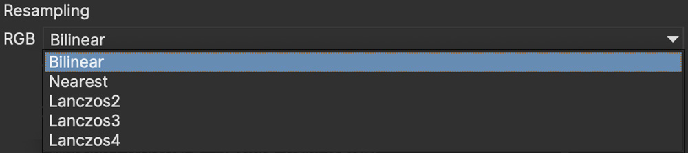
Resampling types are:
Bilinear: The default setting. A very common resampling method that produces decent results
Nearest neighbour: Fast, but can be lower quality
Lanczos 2-4: Good for preserving details and minimising artifacts, but can produce ringing on certain images
Ultimately the resampling can be subjective so you may need to test what works best for the given render, but we highly recommend either Bilinear or Lanczos for Insert renders.
The Mega Plate Module
| This section only relates to Mocha Pro. This feature is not available in Mocha HitFilm or Mocha AE. For a full comparison of features, please refer to the comparison chart online. |
Overview
The Mega Plate module is designed to build complete scenes from your footage to create large clean plates for the purpose of inserting and removing.
Once rendered, Mega Plates can be used as a regular oversized clean plate in the Remove module (otherwise known as a Mega Clean Plate), or exported to be used as a background insert.
Much of the workflow is similar to the Remove Module in that you track areas of the scene and can also remove foreground objects,
but the main goal is to make a full picture of the scene from the moving camera.
| The Mega Plate module is GPU optimised. Make sure you have GPU processing turned on in the 'GPU' page of Preferences for optimal results. |
The Mega Plate Building Process
Mega Plates require a few simple steps to work correctly. The key to a good Mega Plate is a series of one or more tracked backgrounds and masked foreground objects.
The final rendered plate will be centred on the original source frame you rendered from, in order to line up the plate correctly for further work.
| Since the final mega plate is centred on the frame you rendered on, there may be a large amount of alpha padding to one side of your resulting render. To reduce this, aim to render from a frame that is approximately in the middle of the camera motion. |
1. Identify your foreground and background planes
First of all, scrub through your timeline and identify the planes of depth within your shot.
Background often consists of multiple planes of motion, and there can also be obstructing foreground material.
For example, in the shot below, the snowboarder is in front of the mountains.

2. Track and roto your foreground elements
We handle the foreground first as we need to mask them off from the background plane and from each other.
You don’t actually need to worry too much about tracking the foreground:
If the object is untrackable for whatever reason, just hand-animate a spline around it.
You absolutely must track an object if it is going to be used to build the actual Mega Plate.
For more information on effective tracking, please refer to the tracking section of the documentation.
In the example below, we have tracked and rotoscoped the snowboarder which would otherwise obscure the mountains.
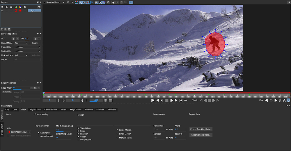
3. Make sure your layer order is correct
Layer order matters in Mocha. The closer to the camera an object is, the higher in the layer stack it should be. Far background should be on the bottom layer, foreground objects should be on top, in order of closeness.
In the example here, we show the snowboarder layer is above the mountains layer
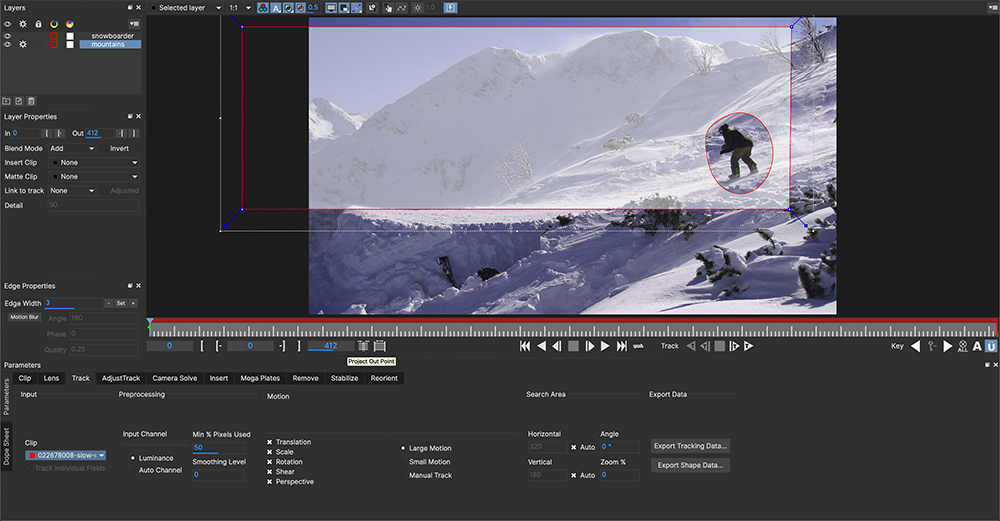
4. Track your background planes
Once you have your foreground objects masked out across the timeline, draw as big a shape as possible. Make sure the background layer is under the foreground layers, and track.
For multiple planes of background, such as a floor and a wall, you will have to track two separate planes of motion. You must specifically track the background layer in order for the Mega Plate build to work.
Here we can see the background mountains tracked at the bottom of the layer stack, covering the large area of mountains in the distance:

5. Adjust the size of your Mega Plate layer mattes
Once tracked, Mega Plates will only build the plate within the confines of the layers you want to use.
Because of this, you want to expand the size of your matte to accommodate the final render.
In the image below, we expand out the matte to approximate the size of the final built plate.

| Don’t make your layer TOO big! If there is a widely distorting perspective track, the matte may become too distorted and Mega Plates will not be able to build a full plate. |
6. Turn on the cogs of the background layers you want to build from and adjust your parameters
Switch to the Mega Plate tab and adjust your parameters (see Mega Plate Parameters below).
Key things to focus on are:
Your search range
Whether to autoscale based on the data or define a final mega plate size
If you need to use an illumination model.
We recommend trying to build a Mega Plate with Illumination modelling set to None first. This is the fastest setting for rendering, and can quite often be all you need if there is not much light difference in the background over time.
7. Render
Once your layers are ready and the parameters are set, click the render button.
This will generate a large plate either based on your own dimensions, or autoscaled if you have set Autoscale on:

Depending on what frame you render your plate, there may be a large amount of alpha padding to one side of the plate.
To avoid this, try rendering from the middle of the overall camera motion.
For example, in a simple left-to-right pan, render on the frame that is in the centre of the pan to fill out more the detail to either side of the centred frame.
| Building a Mega Plate can be a slow process depending on the resolution of the footage and the amount of frames you are building from. You can optimize your search range (see Mega Plate Parameters below) but keep in mind that build quality can vary. |
8. Remove foreground objects (optional)
When you have rendered your plate, you can then try to remove the foreground object from the resulting image:
Select the foreground objects by turning on their cogs
Click "Remove foreground" to initiate the removal.
Note that standard rules for removing foreground apply. See The Remove Module for more information on removing foreground objects.
The background layers you generated the Mega Plate with must be encompassing the foreground layers in order to remove them.
In the image below, we see the snowboarder layer is sitting over the mountain layer and can there fore be removed:

9. Create a Mega Clean Plate
Now that you have rendered a final image, with or without removing the foreground objects from the plate, you can then turn it into a clean plate clip and save it to disk.
To do this:
Scrub to the frame you rendered a Mega Plate
Click the "Create" button under the Clean Plate clip settings in the bottom left of the module parameters
Save the Mega Clean Plate to your preferred place on disk
This will create a Mega Clean Plate clip which can now be referenced by the Remove module.

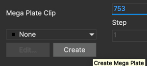
Mega Plate vs Mega Clean Plate - What is the difference?
With all these "Mega" terms floating around let’s clarify what we mean by the two terms:
Mega Plate
The Mega Plate is the large scene generated by the Mega Plate module. This is essentially using parameters similar to the Remove module to make a full representation of the entire tracked footage.
Mega Clean Plate
This is a frame or series of frames that are saved to disk from the Mega Plate render for the purpose of painting or "cleaning up" (thus the term "Clean Plate").
The Mega Clean Plate clip created from Mega Clean Plates is what is referenced by the Mocha Remove module to help replace pixels.
The Mega Plate makes the Mega Clean Plate
To distinguish the three steps clearly:
You generate a Mega Plate from the tracked scene
You create a Mega Clean Plate from the generated Mega Plate and save it to disk for further editing/cleaning
The Remove module can use the Mega Clean Plate for further work.
Mega Plate Troubleshooting
One or more background layers must be defined that include all areas that the foreground object moves across during the shot.
To get the result you expect you should observe the following rules:
If you are getting a large amount of alpha padding to one side of the plate, try rendering from the middle of the camera motion. For example, in a simple left-to-right pan, render on the frame that is in the centre of the pan to render the detail to either side of the centred frame.
As the tracker computes the motion of planar objects in the scene, you get the best results if the background is planar, or it has been subdivided into planar elements. Otherwise you might see artifacts.
If Mocha Pro cannot track the background accurately you will probably get artifacts. If your selection of the background includes objects that move differently to the background this can reduce the accuracy of the computed motion.
If your selection of the background includes parts of the foreground objects then this can cause problems for the tracker as it will compute a motion for the background that is influence by the movement of the foreground. This may also cause artifacts when the Mega Plate render is performed.
If the background contains e.g. a waterfall or another object that changes appearance from frame to frame, you will most likely get artifacts if you try to build a plate or remove an object that moves across such a background. Mocha Pro will not know how to handle the changes. Another cause of such artifacts is moving specular reflections.
Mega Plate Parameters
Here we provide a breakdown of each Mega Plate parameter and how to use it effectively.

When changing parameters in Mocha Pro the change only affects the currently selected layer. To change the parameters of a layer other than the currently selected layer that layer must first be selected.
Input Tab
Here you specify the input clip for the mega plate process and any cleanplates you wish to import.
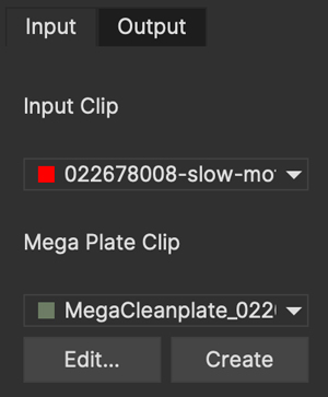
Input Clip
You can choose from any of the Mocha Pro result clips to be used as the source clip to fill the requested layers, instead of the default, which is to use the originally imported clip as the input clip. This can be useful if you have to do multiple passes to get an effective plate.
Cleanplates
Here you can import Mega Clean Plates to replace frames in your footage via the Remove module. Note that in order to tell Mocha the plate is oversized (i.e doesn’t match the original project source dimensions), import the plate from the Mega Plates module rather than the Remove module.
If you import the Mega Plate via the Remove module, Mocha will ask you if you want to create a Mega Clean Plate clip.
To import one or more cleanplates:
Click on Import. This pops up the Cleanplates window.
Click on the file Import… button to specify the file(s) you want to use. If they are numbered in the same way as the input clip, they will be given corresponding frame numbers. Otherwise, edit the Frame Number field for each cleanplate to set up the correct frame number. The entries for two cleanplates will look like this:

By default the Preview option is switched on. This means that the selected (highlighted) cleanplate will be shown in the display window. The current frame viewed on the timeline is also changed to the selected cleanplate frame. When Preview is switched off, the view switches back to the clip you are viewing.
Click on the File name or Frame Number for any cleanplate to change the selection. The Preview option allows you to select the correct frame number for your cleanplate(s). If you import a single cleanplate, the frame number will be listed as "All". This means that the cleanplate will be used for all the frames of the clip. Use this option if the camera is locked off. Change "All" to a particular frame if want to change this behavior and track the cleanplate from the specified frame into the other frames.
| The All option only applies when you are using a single cleanplate. |
If you import two or more cleanplates, Mocha Pro will try to guess the frame numbers from any numbering in the file name. When using the cleanplates between those frame numbers, Mocha Pro will blend the nearest two cleanplates to produce a smooth transition through the clip.
If you want to change the cleanplate settings after exiting the cleanplate window, click on Edit… You would need to do this if you are using the frames on a new machine where the cleanplates are stored in a different location, or just to add new cleanplates. If you re-import files with the same name but different directory to existing cleanplate files, Mocha Pro will update the file to the new directory.
Create (Mega Clean Plate)
Once you have rendered a Mega Plate within Mocha Pro you can create a Mega Clean Plate from the currently viewed frame.
To do this, make sure you are viewing a frame you have rendered and click on the Create button. This will create a clip containing the rendered frame you are viewing, and set the Cleanplates clip to the new clip. You can then touch up this Mega Clean Plate from your saved folder.
When you save your edits, it will automatically be updated in Mocha Pro to be used in the Mega Clean Plate list.
| Creating a Mega Clean Plate in the Mega Plate module does NOT use that clean plate for subsequent renders in the Mega Plate module. To use a Mega Clean Plate, switch to the Remove module. |
Output Tab
This assigns an output clip for the render. You can create new output clips if needed here.
Search Range
Used to specify which frames should be used when building a Mega Plate. The First Frame, Last Frame, # Frames Before and# Frames After settings can be keyframed.
First Frame and Last Frame specify an absolute range in the input clip
# Frames Before and # Frames After settings specify the range relative to the currently rendered frame. If both options are used the intersection of the two frame ranges is used.
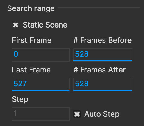
Step
With this option you can specify that not every frame in the reference range is to be used.
Setting it to three, for instance, means that only every third frame will be accessed.
This feature can speed up the removal process for large projects, especially film projects, which are very memory intensive.
| Setting a step value can skip over clean plates for specific frames causing them to not be used in the Mega Plate calculation. |
Auto Step
This is an automatically calculated version of the manual Step field. If you’re not quite sure what step is optimal,
Auto Step will look at the motion of the layers and try to determine the best step to use.
Illumination Model
This specifies how to model changes in illumination.

The None option will not model changes, giving you a result very quickly.
Linear will model global changes and should hence be used if the brightness change between frames are caused by e.g. changes in aperture.
Interpolated will model global and local changes and is often useful when there are erratic lighting changes or a clean plate is used.
Smoothing Level
This controls the amount of smoothing applied in the Interpolated model. Increase the value if there are artifacts which might be resolved with more smoothing, either spatial variations or temporal variations.
Blend Interior
This option causes pixels from different frames to be blended into each other to avoid tearing artifacts inside the Mega Plate.
Blend Amount
Select either Blend or Randomize and increase the value to reduce artifacts which sometimes can be seen when illumination modelling fails.
Blend uses alpha blending from the replaced areas to either the original pixels or the recently replaced areas.
Randomize mixes original and replaced pixels in a random way to achieve a similar effect.
3D Compensation
3D compensation can be switched on to try to remove artifacts due to the background layer not being planar.
For example, if you have tracked a background that has subtle parallax it can cause removal in other frames to look incorrect. 3D compensation attempts to model the parallax change in the target frame.
Flood Fill
If part of the missing background has not been found anywhere in the clip, and the plate cannot be completely built, Flood Fill can be switched on to fill the remaining region using a flood fill method.
Mega Cleanplates
Remove Foreground
This button will remove any foreground objects in the Mega Plate.
To remove foreground layers in a mega plate:
Render the mega plate first using your background layers by selecting the layer processing cogs and pressing the render button
Switch on the cogs of the foreground layers you want to remove
Press
Remove Foreground
Any layers selected will then remove the underlying foreground objects from the mega plate, providing they have removable background behind them.
See the Remove Module documentation for more information on how foreground objects are removed with background data.
Autoscale
On by default, this option will automatically calculate the required size of the plate. If unselected, the dimensions in the fields below the autoscale option will be used.
| If you don’t have enough memory to build the autoscaled plate, Mocha will automatically reduce the size of the plate to fit the available memory. |
Tips for Mega Plates
Some of the foreground object is still visible after using Remove Foreground.
Remember that you can only remove an object if the background behind it is also tracked. Track the background layer(s) before removing a foreground object.
Check that the object is inside the selection contour in every frame. If it isn’t, move the control points outwards as necessary to completely enclose the object. Use linking forwards/backwards to apply changes to the contour in multiple frames.
Check whether the relative motion of the foreground and background layers is sufficient to see "behind" the whole of the foreground object. Mocha Pro only needs to see the background in one frame to achieve good results. If more images are available in the clip, track the selections over a few more images. This may provide Mocha Pro with the extra information it needs.
Try pulling the selection contour closer to the edge of the object. This will provide Mocha Pro with extra background pixels.
The built Mega Plate is brighter/darker in sections rather than being evenly lit.
Changes in illumination or camera aperture will change the overall brightness of the image, making direct replacement of pixels inappropriate. Select the Linear illumination model to compensate for the brightness changes and repeat the render.
If the variation is more complex than a simple brightness change, try the Interpolated illumination model, which will compute and compensate for changes in apparent brightness and color that vary across the region being built.
Some Mega Plate sections don’t line up with the rest of the image.
This may be due to inaccurate tracking of the background. If you think this is possible, see the above hints on improving the tracking.
If the tracking accuracy cannot be improved, increase the
Blend amount. This will dissolve the plate sections into the original image and reduce the tearing artifacts.For small foreground objects such as wires, in front of a non-planar background, switch on 3D Compensation. This will attempt to model the effect of the varying 3D depth of the background.
If there is more than one background selection, special treatment of the boundary between them is often required. If the background layers are joined, such as a wall and floor selection, use the Attach Layers tool to join them together and avoid artifacts at the boundary. If they are moving independently, you need to adjust the boundary in the front background selection to accurately delineate the boundary between the two background selections.
Render is slow.
If you have a long clip, especially working with high resolution footage, Mega Plate renders can be slow because Mocha has to search over a large number of images with a large memory footprint.
Before you change any settings in the Mega Plate parameters, it is worthwhile checking to see if GPU Processing is turned on in Preferences under the GPU page.
GPU Processing can have a significant impact on your render times.
Mega Plate and Remove are the most memory intensive modules in Mocha Pro, and it will always benefit the performance to add more memory.
If Mocha Pro can fit all the images it needs in memory, performance will be dramatically accelerated when rendering Mega Plates with multiple frames, because it will minimize the amount of disk accesses.
Your aim should be where possible to change the settings to achieve this:
Change the First Frame and Last Frame in Range to a smaller range of frames. Experiment by reducing the range of frames searched.
Increase the Step in Range to sample less frames.
Create clean plates on key frames (such as the start, middle and end of the shot, or wherever there is significant change) and check "Use Cleanplates Exclusively" to reduce the need to look for other frames.
Using Mega Clean Plates in the Remove Module
Ultimately once you have created a Mega Clean Plate, it can be used as a single clean plate for your scene.
This means you can paint on one large plate and then reference only this clean plate in remove, by turning on "Use cleanplates exclusively".
To use the Mega Clean Plate in the Remove module:
Follow the Mega Plate rendering procedure listed above
Create the Mega Plate (step 9 of the process)
Make any changes to the clean plate you need in your image editor
Switch to the remove module in Mocha
Create a foreground layer if one doesn’t exist yet then select the foreground
Choose the Mega Clean Plate clip from the "Cleanplate Clip" section
Select "Use Cleanplates Exclusively"
Render forwards
Any changes you have painted into the clean plate will then be applied across the whole timeline.
For more details on how to use clean plates in the Remove module, see The Remove Module section.
Examples of Using Mega Clean Plates in compositors
You can also import the rendered Mega Plate into a compositor and use the Mocha tracking data to align the plate.
Below are some basic examples of how to do this.
Inserting a Mega Clean Plate into an After Effects Composition
You can insert a Mega Plate into an After Effect composition the same way as you do with a regular insert.
However, since the Mega plate will always be larger than your original composition, you need to do some extra steps to set up the plate:
Export the mega plate to disk, either by creating a clean plate in the Mega Plates module or exporting the single frame in Export Rendered Clips.
Align your Surface to the frame you used to create the mega plate. For example, if you rendered a Mega Plate on frame 200, align the surface to frame 200.

Go to
Export Tracking Dataand exportAfter Effects CC Power Pin(or Use Create Track Data in the Mocha Adobe Plugin)Import the mega plate into After Effects and drag it to your composition
Precompose the mega plate and select the
Leave All Attributesoption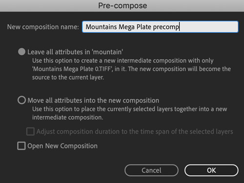
Turn on
Collapse Transformationson the new precomp layer
Apply the CC Power Pin track data to the mega plate precomp layer, either by pasting from the clipboard or using "Apply Export" in the Mocha Pro Adobe plugin.
Now the corner pin will be applied to the precomped layer, but with the Collapse Transformations option set, the whole plate will be distorted in place.
Inserting a Mega Clean Plate into a Nuke node graph
You can insert a Mega Plate into Nuke the same way as you do with a regular insert.
However, since the Mega plate will always be larger than your original composition, you need change to do some extra steps to set up the plate:
Export the mega plate to disk, either by creating a clean plate in the Mega Plates module or exporting the single frame in Export Rendered Clips.
Align your Surface to the frame you used to create the mega plate. For example, if you rendered a Mega Plate on frame 200, align the surface to frame 200.
Go to
Export Tracking Dataand exportNuke Corner PinIn Nuke, import your original footage to a read node
Paste the corner pin into the node graph. If the "From" fields in your corner pin are not set to the original footage size, set them now.

Import the mega plate to a new read node
Apply a Reformat node to the mega plate to fit to the project size, but set the Resize type to "None"

Cut and paste the corner pin to mega plate or just hook up the inputs
Merge the mega plate over the top of your original footage.

'''
The Remove Module
| This section only relates to Mocha Pro. This feature is not available in Mocha HitFilm or Mocha AE. For a full comparison of features, please refer to the comparison chart online. |
Overview
The remove module is designed to remove foreground objects from your footage to create clean plates. A removed object can be anything: wires, poles, signs, people and so on. The only requirement for a good removal is enough background to use.
To understand how Mocha Pro removes a foreground object consider how you would do it yourself. A common method is to select a source image where the foreground object does not obscure the background region you are trying to paint in the target frame. You would then clone or otherwise copy the pixels from the source frame to the target frame. If the background is not in the same position in the two frames you would have to track the patch of pixels into the frame, and if the lighting is different between the two frames you would have to adjust the brightness of the patch.
The remove module attempts to do this for you automatically using a method called motion keying. As it has tracked the background areas you have defined, it can move pixels of these background areas from one frame to another. Hence, if a part of a background area is obscured in one frame, Mocha Pro can search the rest of the clip for a frame where the obscured background area is visible, and move the pixels correctly into the target frame. During this process Mocha Pro will evaluate and compensate for the lighting differences between the source and the target frame.
| The Remove module is GPU optimised. Make sure you have GPU processing turned on in the 'GPU' page of Preferences for optimal results. |
The Removal Process
Object removal requires a few simple steps to work correctly. The key to a good remove is adequate, tracked background and a correctly masked foreground.
The only time you don’t need a tracked background is if you have a static (locked) scene. See the Static Scene option for more details.
1. Identify your foreground and background planes
First of all, scrub through your timeline and identify the planes of depth within your shot. Background often consists of multiple planes of motion, and there can also be obstructing foreground material. For example, in the shot below, the sign is in front of the ground, and the car door is in front of (but not obscuring) the sign.
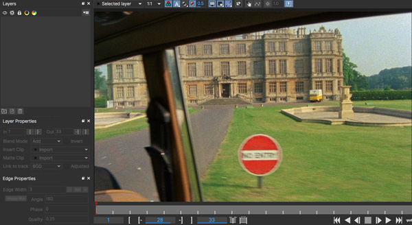
2. Track and roto your foreground elements
We handle the foreground first as we need to mask them off from the background plane and from each other. You don’t actually need to worry too much about tracking the foreground: If the object is untrackable for whatever reason, just hand-animate a spline around it. You absolutely must track an object if it is going to be used as a background pass to replace foreground. For more information on effective tracking, please refer to the tracking section of the documentation.
In the example below, we have tracked and rotoscoped the sign and the door frame, which would otherwise obscure the ground plane.
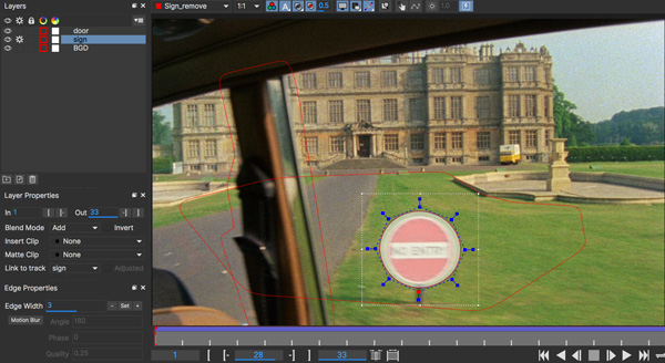
3. Make sure your layer order is correct
Layer order matters in Mocha. The closer to the camera an object is, the higher in the layer stack it should be. Far background should be on the bottom layer, foreground objects should be on top, in order of closeness.
In the example here, we show the door layer is above the sign layer, and the sign is above the ground layer in the stack.
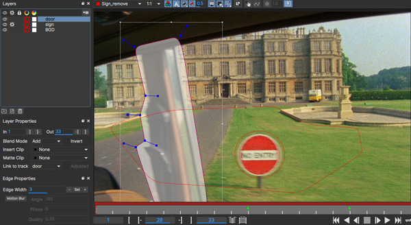
4. Track your background plane
Once you have your foreground objects masked out across the timeline, draw as big a shape as possible to cover as much of the possible area you want to remove. Make sure the background layer is under the foreground layers, and track. For multiple planes of background, such as a floor and a wall, you will have to track two separate planes of motion. You must specifically track the background layer in order for the removal to work, even if you are working with a locked-off shot.
Here we can see the background drawn on a layer at the bottom of the layer stack, covering the large area of grass.

5. Select the layer you want to remove and adjust your removal parameters
Switch to the remove tab and adjust your parameters (see Remove Parameters below). Key things to focus on are your search range, whether or not you need to create or adjust a cleanplate, and if you need to use an illumination model.
We recommend trying a remove with Illumination modeling set to None first. This is the fastest setting for removals, and can quite often be all you need if there is not much light difference in the background over time.
6. Render
Once your layers are ready and the parameters are set, click the render button or render forward.

| Removal can be a slow process depending on the resolution of the footage and the amount of frames you are removing on. You can optimize your search range (see Remove Parameters below) but keep in mind that removal quality can vary. |
Removal Troubleshooting
One or more background layers must be defined that include all areas that the foreground object moves across during the shot.
To get the result you expect you should observe the following rules:
As the tracker computes the motion of planar objects in the scene, you get the best results if the background is planar, or it has been subdivided into planar elements. Otherwise you might see artifacts.
If Mocha Pro cannot track the background accurately you will probably get artifacts. If your selection of the background includes objects that move differently to the background this can reduce the accuracy of the computed motion.
If your selection of the background includes parts of the foreground objects then this can cause problems for the tracker as it will compute a motion for the background that is influence by the movement of the foreground. This may also cause artifacts when the removal is performed.
If the background contains e.g. a waterfall or another object that changes appearance from frame to frame, you will most likely get artifacts if you try to remove a foreground object that moves across such a background. Mocha Pro will not know how to handle the changes. Another cause of such artifacts is moving specular reflections.
Remove Parameters
Here we provide a breakdown of each remove tool parameter and how to use it effectively.

When changing parameters in Mocha Pro the change only affects the currently selected layer. To change the parameters of a layer other than the currently selected layer that layer must first be selected.
Input Tab
Here you specify the input clip for the remove process and any cleanplates you wish to import.
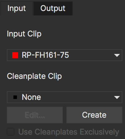
Input Clip
You can choose from any of the Mocha Pro result clips to be used as the source clip to fill the requested foreground layers, instead of the default, which is to use the originally imported clip as the input clip. This can be useful if you have to do multiple passes to get an effective remove.
Cleanplates
Here you can import cleanplates to replace frames in your footage. If you don’t have enough background to use in your shot, importing your own cleaned up version of a frame can assist the remove tool greatly.
To import one or more cleanplates:
Click on Import. This pops up the Cleanplates window.
Click on the file Import… button to specify the file(s) you want to use. If they are numbered in the same way as the input clip, they will be given corresponding frame numbers. Otherwise, edit the Frame Number field for each cleanplate to set up the correct frame number. The entries for two cleanplates will look like this:
By default the Preview option is switched on. This means that the selected (highlighted) cleanplate will be shown in the display window. The current frame viewed on the timeline is also changed to the selected cleanplate frame. When Preview is switched off, the view switches back to the clip you are viewing.
Click on the File name or Frame Number for any cleanplate to change the selection. The Preview option allows you to select the correct frame number for your cleanplate(s). If you import a single cleanplate, the frame number will be listed as "All". This means that the cleanplate will be used for all the frames of the clip. Use this option if the camera is locked off. Change "All" to a particular frame if want to change this behavior and track the cleanplate from the specified frame into the other frames.
| The All option only applies when you are using a single cleanplate. |
If you import two or more cleanplates, Mocha Pro will try to guess the frame numbers from any numbering in the file name. When using the cleanplates between those frame numbers, Mocha Pro will blend the nearest two cleanplates to produce a smooth transition through the clip.
If you want to change the cleanplate settings after exiting the cleanplate window, click on Edit… You would need to do this if you are using the frames on a new machine where the cleanplates are stored in a different location, or just to add new cleanplates. If you re-import files with the same name but different directory to existing cleanplate files, Mocha Pro will update the file to the new directory.
Create (Cleanplate)
| Clean plates are created based on the bit depth of the current source clip. |
One useful option within Mocha Pro is to create a cleanplate from the currently viewed frame.
To do this, make sure you are viewing the frame you want to use and click on the Create button. This will create a clip containing the frame you are viewing, and set the Cleanplates clip to the new clip. You can then touch up this cleanplate from your Results folder.
The frame that is saved will be based on the current bit depth of the source clip, which will change the image format.
For low bit depth clips, this will either be tif (the default), or dpx. For float, this will be exr or tif.
You can change to the preferred image type in preferences under the clip tab.
When you save your edits, it will automatically be updated in Mocha Pro to be used in the cleanplate list.
Use Cleanplates Exclusively
If this option is checked, only the cleanplates will be used by Remove to remove the pixels in the selected layer. If it is unchecked, the normal Remove process will be used, pulling in pixels from other frames in the input clip. The cleanplates will then only be used to remove the remaining pixels.
Output Tab
This assigns an output clip for the removal render. You can create new output clips if needed here.
Search Range
Used to specify which frames should be used when removing a layer. The First Frame, Last Frame, # Frames Before and# Frames After settings can be keyframed.
First Frame and Last Frame specify an absolute range in the input clip
# Frames Before and # Frames After settings specify the range relative to the currently rendered frame. If both options are used the intersection of the two frame ranges is used.
This checkbox tells Mocha there is no moving background behind the current layer (for example a moving object in a locked shot), so it doesn’t require a background layer to remove.
| If you use the "Static Scene" checkbox, you don’t need to track a background layer. This is the only scenario where a background tracked layer is not required. |
Step
With this option you can specify that not every frame in the reference range is to be used.
Setting it to three, for instance, means that only every third frame will be accessed.
This feature can speed up the removal process for large projects, especially film projects, which are very memory intensive.
| Setting a step value can skip over clean plates for specific frames causing them to not be used in the Remove calculation. |
Auto Step
This is an automatically calculated version of the manual Step field. If you’re not quite sure what step is optimal,
Auto Step will look at the motion of the layers and try to determine the best step to use.
Illumination Model
This specifies how to model changes in illumination.
The None option will not model changes, giving you a result very quickly.
Linear will model global changes and should hence be used if the brightness change between frames are caused by e.g. changes in aperture.
Interpolated will model global and local changes and is often useful when a cleanplate is used.
Smoothing Level
This controls the amount of smoothing applied in the Interpolated model. Increase the value if there are artifacts which might be resolved with more smoothing, either spatial variations or temporal variations.
Blend Interior
This option causes pixels from different frames to be blended into each other to avoid tearing artifacts inside the Remove area.
Blend Amount
Select either Blend or Randomize and increase the value to reduce artifacts which sometimes can be seen when illumination modelling fails.
Blend uses alpha blending from the replaced areas to either the original pixels or the recently replaced areas.
Randomize mixes original and replaced pixels in a random way to achieve a similar effect.
3D Compensation
3D compensation can be switched on to try to remove artifacts due to the background layer not being planar.
For example, if you have tracked a background that has subtle parallax it can cause removal in other frames to look incorrect. 3D compensation attempts to model the parallax change in the target removal frame.
Flood Fill
If part of the missing background has not been found anywhere in the clip, and the foreground object therefore cannot be completely removed, Flood Fill can be switched on to fill the remaining region using a flood fill method. This is especially useful when it is the matte you are interested in, as you then don’t care too much about the quality of the removal but require that the foreground object is completely removed to avoid holes in the matte. The Smoothing Level should be increased if you result is not as smooth as it should be or there are temporal variations in the results.
Stereo Remove
Stereo Remove works in exactly the same way as Mono Remove above, with the additional bonus of being able to render both views at the same time and also choosing whether or not each view assists the other view during the remove process.
Track the background in both views with a layer as outlined in "Stereo Tracking" above
Mask out and animate the foreground object you want to remove. You will need to check to make sure the object is correctly covered by the layer in both views.
Make sure the foreground layer is above the background layer in the layer controls.
Adjust your remove parameters (See the full User Guide for details on Remove parameters)
If it is not already on, press the "Operate in all views" button on the right side of the render buttons.
Click the render button

By default "Prefer Same View" is checked on in the search range section of the Remove tab. This will attempt to use the current view rather than both views to perform the remove.
If you have useful information in the other view that may assist the remove, you can uncheck this option.
Tips for Removal
Some of the object is still visible after removal.
Remember that you can only remove an object if the background behind it is also tracked. Track the background layer(s) before removing a foreground object.
Check that the object is inside the selection contour in every frame. If it isn’t, move the control points outwards as necessary to completely enclose the object. Use linking forwards/backwards to apply changes to the contour in multiple frames.
Check whether the relative motion of the foreground and background layers is sufficient to see "behind" the whole of the foreground object. Mocha Pro only needs to see the background in one frame to achieve good results. If more images are available in the clip, track the selections over a few more images. This may provide Mocha Pro with the extra information it needs.
Try pulling the selection contour closer to the edge of the object. This will provide Mocha Pro with extra background pixels.
The replaced background region is brighter/darker than the surrounding image.
Changes in illumination or camera aperture will change the overall brightness of the image, making direct replacement of pixels inappropriate. Select the Linear illumination model to compensate for the brightness changes and repeat the object removal.
If the variation is more complex than a simple brightness change, try the Interpolated illumination model, which will compute and compensate for changes in apparent brightness and color that vary across the region being removed.
The background patches don’t line up with the surrounding image.
This may be due to inaccurate tracking of the background. If you think this is possible, see the above hints on improving the tracking.
If the tracking accuracy cannot be improved, increase the Dissolve Width. This will dissolve the patches into the original image and reduce the tearing artifacts.
For small foreground objects such as wires, in front of a non-planar background, switch on 3D Compensation. This will attempt to model the effect of the varying 3D depth of the background.
If there is more than one background selection behind the foreground selection, special treatment of the boundary between them is often required. If the background layers are joined, such as a wall and floor selection, use the Attach Layers tool to join them together and avoid artifacts at the boundary. If they are moving independently, you need to adjust the boundary in the front background selection to accurately delineate the boundary between the two background selections.
Remove is slow.
If you have a long clip, especially working with HD or film, Remove can be slow because it has to search over a large number of images with a large memory footprint.
Before you change any settings in the Remove parameters, it is worthwhile checking to see if GPU Processing is turned on in Preferences under the GPU page.
GPU Processing can have a significant impact on your render times.
Remove is the most memory intensive module in Mocha Pro, and it will always benefit the performance to add more memory.
If Mocha Pro can fit all the images it needs in memory, performance will be dramatically accelerated when rendering Remove in multiple frames, because it will minimize the amount of disk accesses.
Your aim should be where possible to change the settings to achieve this:
Change the First Frame and Last Frame in Range to a smaller range of frames. Sometimes Mocha Pro can spend a lot of time removing a small part of the foreground image, and if your layers were chosen loosely, not all of the foreground needs to be removed. Experiment by reducing the range of frames searched.
Increase the Step in Range to sample less frames.
Create clean plates on key frames (such as the start, middle and end of the shot, or wherever there is significant change) and check "Use Cleanplates Exclusively" to reduce the need to look for other frames.
'''
The Stabilize Module
Overview
| Some features in this section only relate to Mocha Pro. The Stabilize module is unsupported for 360 Equirectangular footage in VR Mode. Use the Reorient module to stabilize 360 footage. This feature is not available in Mocha HitFilm or Mocha AE. For a full comparison of features, please refer to the comparison chart online. |
The stabilize feature in uses the data you have tracked to lock down a moving shot. You can think of it as the inverse of what tracking does: It moves the footage around an area rather than an area around the footage. Stabilization is useful for:
Removing camera jitter and bumps
Locking off a shot so it is easier to work with, before restoring the motion back into the final composition
The Main Stabilization Parameters Interface
Stabilization is a fairly straightforward operation. Once you have selected the tracked layer you wish to work with you have options to restrict the stabilization to key details.

Input Tab
Select the clip that you wish to use to stabilize here.

Range Tab
Select the frame range for the stabilization.
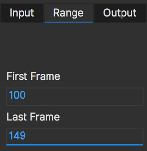
Fixed Frames
Here you can enter the frames you want to be unaffected by stabilization. Mocha will adjust the stabilization between these frames. You can either enter them into the field, or go to a frame and press the + key.

Fixed frames can be useful when you want stabilization across a shot but would like to keep the general motion of the original shot intact.
When using Warp Mapping, the fixed frames list is limited to one frame. Warping is reset to warp from that frame.
Smooth
This is the main section for controlling how you want the shot to stabilize.

All Motion
This checkbox sets all the options below it.
X Translation
Stabilize translation in X
Y Translation
Stabilize translation in Y
Rotation
Stabilize rotation
Zoom
Stabilize the scale/zoom
X Shear
Distort the footage according to the tracked surface’s shear data in X
Y Shear
Distort the footage according to the tracked surface’s shear data in Y
X Perspective
Distort the footage according to the tracked surface’s perspective data in X
Y Perspective
Distort the footage according to the tracked surface’s perspective data in Y
Shear and Perspective stabilization can be useful when you want to straighten out a plane in your footage to work on it flat before restoring it to its original perspective and motion.
Maximum Smoothing
Stabilize across the entire track. Setting this value will override the #Frames value beneath it.
# Frames
Stabilize variation across a certain amount of frames. Setting this to a low value will focus the stabilization to only pick up motion that occurs in short bursts (such as a bump in the road). A higher value will try to adjust longer movements.
Warp Mapping
Warp Mapping utilizes the PowerMesh tracking to lock down warping areas.
Warp Mapping parameters
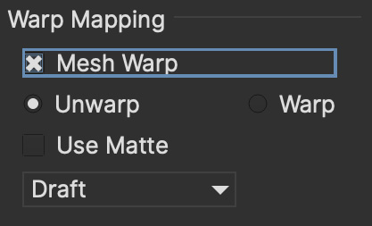
To use warp mapping:
Track using the Mesh tracking parameter in the Track Module
Switch to Stabilize
Turn on "Mesh Warp" under the Warp Mapping column
Choose if you want to add a fixed frame to the Frame List
Choose whether you want to Unwarp or Warp to the tracked area
Check "Use Matte" if you want to matte out the stabilized region
Choose the render quality in the drop down
Warp Mapping will preview in the Viewer.
The Warp Mapping Parameters have the following effects:
Mesh Warp
This turns on the Warp Mapping. When it is turned off, Stabilize will use regular the regular planar stabilization controls.
Unwarp
Unwarp locks the frame to the "Fixed Frame" value set in "Frame List" to the right of the stabilize module parameters.
By default, this is set to the frame the PowerMesh frame was generated on.
Warp
This is the inverse of the Unwarp render. It warps the area to the motion of the tracked mesh.
Use Matte
The Matte uses the warped layer matte to mask out the warped region.
Quality
You can set 3 types of render quality for Warp Mapping:
Draft: A very fast render preview, but lower quality. Draft can produce triangulation on warped edges and is not recommended for final renders.
Normal: A balance of render quality and speed.
High: A much denser render warp mapping that produces high quality results but will render slower.
Warp Mapping Workflow
You can use warp mapping in two main ways:
Directly applying warping to images or footage with the intention of compositing back over the top of the footage.
Unwarping, editing then rewarping the original footage
Direct Warping Workflow
Direct Warping is the recommended workflow for Warp Mapping as it is a one-way change that avoids losing pixel information.
Warping workflow utilises the singular "Warp" option in Warp Mapping to modify an overlay, usually with alpha.
Direct Warping Workflow in the Plug-In
Apply the Mocha Pro Plug-In to your footage layer or node
Open the Mocha GUI
Track the area you want to stabilize using the Mesh option
Switch to Stabilize and turn on "Mesh Warp"
Preview the warp and unwarp
Close and save the project
Create an overlay clip or image that you want to warp to the original shot.
From there, the workflow can depend on the host you’re using the Plug-In with:
Create a new layer above the source footage track using the overlay image you want to warp over your footage,
Copy the Mocha Pro effect that contains your tracked mesh data
Paste the Mocha Pro Plug-In to the overlay image as a new layer above the source image.

In the Mocha Pro Plug-In interface, select "Stabilize: Warp" from the Module render drop down.
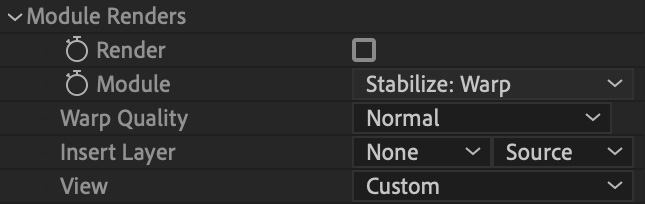
If required, turn on "Apply Matte" in the Plug-In to isolate the region
Create a new image/clip node containing the overlay you want to warp over the source.
Copy the Mocha Pro node that contains your tracked mesh data
Paste the Mocha node again and then change the Source input to the overlay image node
In the plug-in interface, select "Stabilize: Warp" from the Module render drop down.
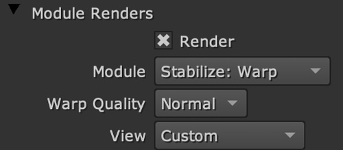
If required, turn on "Apply Matte" in the Plug-In to isolate the region
Use a Merge to composite the warped overlay back on the source

Note than in Fusion you need to make sure single-frame images or effects are read as the same length as your source footage or Mocha may not read the frames.
You can do this via a merge over the top of the original source footage and setting the merge up to only show the foreground. This will then adopt the frames of the footage when you feed the merge into Mocha.
To view the matte masking out the render, you may need to set 'Premultiply Output' from "Auto" to "On":

Create a new video track above the source footage track and place your overlay on this new video track
Drag the Mocha Pro efect that contains your tracked mesh data onto the track above and use the "Apply Mate" to mask RGB items over the top. Keep in mind however than alpha and blending is not supported in Media Composer without addtional plug-ins.
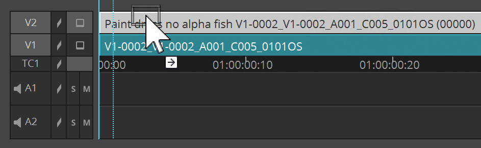
In the plug-in interface, select "Stabilize: Warp" from the Module render drop down.

Turn on "Apply Matte" in the Plug-In to isolate the region
| Avid Media Composer doesn’t currently overlay alpha in the Warp Render, so masking is necessary to composite the warped shot. |
This now warps the image back over the top of the original.
Overlay Images
Overlay images can either be transformed images (for example brand logos) set in place then comped on top of your reference frame, or painted areas on top of a full frame alpha.
As long as the final image matches the dimensions of the original source image, the frame should line up and be warped correctly.
For example, if your shot is 1920x1080, you would want to make a 1920x1080 overlay image and keep alpha in the area you don’t need modified.
You can also choose to just directly paint on top of a single still frame of the source footage and then use the masking tool to mask out the remainder of the frame.
Unwarping and Warping Workflow
When you want to make changes to the pixels of the whole stabilized sequence, the Unwarp/Warp method can be helpful.
It is important to know however that Unwarping and Warping is a destructive process. You may not be able to fully recover pixels lost to Unwarping when you rewarp it back into position.
For example, if you are tracking a person’s eyes opening and closing, the Unwarp process may be able to stabilize the skin until it crunches up and disappears, but rewarping means those stabilized pixels may stretch or tear unnaturally.
This doesn’t of course mean that unwarping and rewarping isn’t a valid approach. You just need to be aware of the limitations.
Unwarp/Rewarp workflow is a 3 stage process:
Render the stabilized and unwarped area
Make modifications to the stabilized region, such as paint, clean up etc
Render a Warp of the modified result to restore back to the original motion.
In the Mocha Pro Plug-In most of this happens in the Plug-In interface.
Unwarp/Rewarp Workflow in After Effects
Apply the Mocha Pro Plug-In to your footage layer
Open the Mocha GUI
Track the area you want to stabilize using the Mesh option
Switch to Stabilize and turn on "Mesh Warp"
Preview the warp and unwarp
Close and save the project
In the plug-in interface, select "Stabilize: Unwarp" from the Module render drop down.
Turn on the Render checkbox. If you scrub the timeline you should now see the unwarp.
Make a copy of the Mocha Pro Plug-In
Precomp your existing layer and move all attributes into the new composition
Paste the copied effect on top of the Precomp
In the plug-in interface for the pasted effect, select "Stabilize: Warp" from the Module render drop down.
Either Turn on "Apply Matte" or use the "Use matte" option in the Warp mapping to isolate the region
Now you can make any changes to the precomped version of the warp and it will rewarp correctly in the parent composition.
Unwarp/Rewarp Workflow in Node-based workflow (Nuke/Fusion/Silhouette/Flame)
Apply the Mocha Pro Plug-In to your footage node
Open the Mocha GUI
Track the area you want to stabilize using the Mesh option
Switch to Stabilize and turn on "Mesh Warp"
Preview the warp and unwarp
Turn on "Use Matte" if you want to matte out the render using the stabilized mask
Close and save the project
In the plug-in interface, select "Stabilize: Unwarp" from the Module render drop down.
Turn on the Render checkbox. If you scrub the timeline you should now see the unwarp.
Make a copy of the Mocha Pro node
Paste the copied node on top of the original
In the plug-in interface for the pasted node, select "Stabilize: Warp" from the Module render drop down.
To view the matte masking out the render, you may need to set 'Premultiply Output' from "Auto" to "On":
Now you can make any changes in the middle of the two Mocha Pro nodes and it will rewarp correctly in the parent composition.
Unwarp/Rewarp Workflow in the Standalone Application
The Standalone application is slightly more involved as you need to use an external application to make any changes to the rendered result.
Track the area you want to stabilize using the Mesh option
Switch to Stabilize and turn on "Mesh Warp"
Preview the Unwarp
Render forwards
Export the clip to a lossless format, such as TIF
Work on the rendered clip
Go to the Clip module in Mocha and Import the modified clip back to your Mocha Project
While in the import dialog, inherit the attributes of the origial clip via the "Inherit Attributes from" dropdown
Go to the Stabilize module and choose the new clip from the "Input" dropdown on the far right
Turn on Warp.
The modified clip should now warp back to the correct spot.
The Borders Tab
This tool helps automate removing the black edges you gain from the footage being stabilize.
Center
This centers the footage around the stabilized area.
Zoom
This zooms into the footage to push the edges out of frame.
Apply Crop
This applies the Clip mask from the Clip Module to crop down the edges.
If this is not applied, the stabilize will render outside the clip mask to the full dimensions of the original source footage.
The Auto Fill Tab
You can use Auto Fill to help fill in the black edges with previously tracked layers, similar to how the Remove Module uses tracked background layers to remove foreground objects.
If you have sufficient usable background available, you can avoid reducing the quality or resolution of footage, which is a common problem in stabilization.
For a better understanding of background fills, please refer to the Remove documentation.
Auto Fill
This turns on the auto fill function. You will not see the effect of fill however until you render the result.
Search Range
The range of frames to look for possible fill frames.
Model Illumination
Like the Illumination modeling in the remove tool, this tries to calculate the correct lighting for a filled-in edge.
Dissolve
This gives the option of dissolving the edge of frame into the filled frame to reduce obvious mismatches.
Fill from Background
If you haven’t set up a tracked background layer to use to help fill the edges, you can let Mocha attempt to fill by analyzing the footage. This is mostly useful for filling in frames where there is only position and rotation jitter.
Stabilizing Shaky Camera Footage
One of the most common reasons to stabilize is to remove jitter from a shaky camera shot. With shaky camera footage you are primarily concerned with removing position and rotation data. This means you do not have to use the shear or perspective options when tracking. Here is the common method:
Track a static area of the shot using Translation, Scale and Rotation only. You don’t want to track a moving object within the shot as this will throw off the stabilization.
Once tracked, switch to the Stabilization tool.
Choose which fields of motion you wish to stabilize in the Smooth parameters. By default, translation is automatically selected. In many cases you may only be interested in position stabilization, but hand-held cameras can introduce scale and rotation jitter as well.
Adjust the number of frames you want to look for jitter over. A small amount of frames will look for tiny adjustments in the overall motion, whereas bigger values in this field will adjust larger ranges of motion.
If there is a significant amount of motion being stabilized and you are losing a lot of your picture in some frames, try fixing those frames by adding them to the Frame List on the left. Mocha will then interpolate the stabilization between these fixed frames.
Locking Down Areas of Motion
Sometimes you want to be able to completely lock down a section of the footage so that it stays in one place and everything else moves around it. For this you can use more aggressive stabilization:
Track the area you want to lock down using whichever of the motion parameters you require. Tracking perspective also works for this technique.
Once tracked, switch to the Stabilization tool.
Choose which fields of motion you wish to lock down in the Smooth parameters. By default, translation is automatically selected. If you want to completely lock down everything, just choose the "All Motion" checkbox.
Adjust the number of frames you want to use to look for stabilization. A small amount of frames will look for tiny adjustments in the overall motion, whereas bigger values in this field will adjust larger ranges of motion. Again, if you want to completely lock down everything for all motion, choose the "Maximum Smoothing" option.
When you play back the timeline you will see the rest of the footage warp and move around your locked off area.
Exporting Stabilized Tracking Data [Mocha Pro]

Exporting Stabilization is similar to exporting tracking. When you hit the Export Stabilized Tracking Data button you will be presented with a dropdown box with options for various applications.
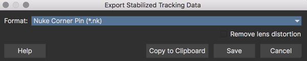
Stabilize in Stereo
All stabilization can occur in stereo if you have tracked both views.
You can render the stabilization for both views by selecting Operate on All Views button next to the Render buttons on the timeline.
The Lens Module
Overview
| Some features in the Lens Module are not available in Mocha HitFilm or Mocha AE and only relate to Mocha Pro (such as rendering). For a full comparison of features, please refer to the comparison chart online. |
The Mocha lens module helps locate and undistort lens distortion.
To compute lens distortion you need an image with one or more distorted straight lines or a distortion map (Mocha Pro only).
For line calibration you can either use your source material if it has suitable lines or take an image of a calibration grid. Using either 1-Parameter or 2-Parameter radial distortion models will allow you to straighten up the image. There is also an Anamorphic model that will accurately model the distortion in anamorphic and extreme wide-angle lenses.
If you have a Distortion Map, you can also remove or work with distortion by importing your maps instead of calibrating.
Distortion of the images can also influence the performance of other modules in Mocha Pro, because the tracker tools assume that the camera obeys a simple pinhole camera model. Severe distortion effects are most likely when a fish-eye or other short focal length lens is used.
Typical lens distortion makes a square object appear either barrel shaped or pin cushion shaped in the image.
The most obvious way to tell whether your images are distorted is to look at the straight edges of objects in the scene. If lines that should be straight are actually curved in the image, this is indicative of distortion. If there are no long straight edges in the scene (for instance a natural scene) then it is much more difficult to discern distortion, even when it is significant.
With the Mocha lens module you can compute, apply and remove distortion automatically. There are two parts to this process – firstly compute the distortion and secondly correct the distortion.
To compute distortion automatically you will need to have some straight lines in your image(s).
It is useful to toggle the grid on and off during the different stages of calibrating the lens to see a visual representation of what is actually happening. Just select the Grid button in the View Controls bar to switch the grid on and off.
Lens Workflow with Line Detection Calibration
Lens calibration is dependent on working with the parameters, which are described in detail below.
The basic workflow for line-based lens calibration is as follows:
Set your input clip and your calibration clip. These can be the same if there are obvious distorted lines in your input clip, but you can also opt to use a Grid Image (see Using Grid Images)
Use the Locate Lines button to find the straight lines in your calibration clip. Adjust the Min Line Length if needed.
Click the new line button (Or press N on your keyboard) and click on line segments to define what should be straight lines. Every time you need to define a new line, make sure you click on the button again or press N.
Once you have defined enough lines, click on the Calibration dropdown and select a camera model (Usually 1-Parameter or 2-Parameter).
If you are calibrating with a grid, choose Equidistant Lines
Click the Calibrate button.
To check the distortion, turn on your grid
Lens Workflow with Layer Splines
The basic workflow for lens calibration using splines is as follows:
Set your input clip and your calibration clip. These can be the same if there are obvious distorted lines in your input clip, but you can also opt to use a Grid Image (see Using Grid Images)
Select the "Use Splines" checkbox
Draw splines to match the curved areas of the shot. With the "Use Layer Splines" turn on, the splines will be open lines instead of closed shapes by default
Once you have defined enough lines, click on the Calibration dropdown and select a camera model (Usually 1-Parameter or 2-Parameter).
If you are calibrating with a grid, choose Equidistant Lines
Click the Calibrate button.
To check the distortion, turn on your grid
You can now choose to render out the distortion, or use the current calibration to assist your tracking and insertion workflow.
For further detail on the calibration tools, see Lens Parameters below.
Equirectangular Lens Workflow with 360 VR
| The Equirectangular and other 360 video features are only available in Mocha Pro and not accessible via other Mocha products such as Mocha AE. |
The first step for working in 360 VR mode is define you are working in Equirectangular space.
Mocha Pro can set this in the New Project dialog on standalone:
Or in the Views drop down in the plugin:
You can also change to Equirectangular in the Lens module:
Go to the Lens module
In the “Calibrate” section, choose “Equirectangular” from the drop down.
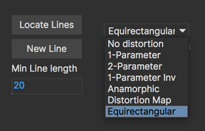
| VR footage with an odd pixel width may not wrap correctly and you could see artifacts. |
And that’s it! You’re now ready to work in VR lens space and don’t need any further calibration. If at any time you want to adjust the 360 view numerically, the fields Longitude, Latitude and Field of View are available to adjust in the Lens page.
Note that if you are rendering a 360 lens distortion in the plugin version, you can control the Lens distortion from the plugin interface without having to open the Mocha GUI.
See Equirectangular Lens Workflow with 360 VR for more details on using the Equirectangular lens calibration effectively.
Lens Parameters
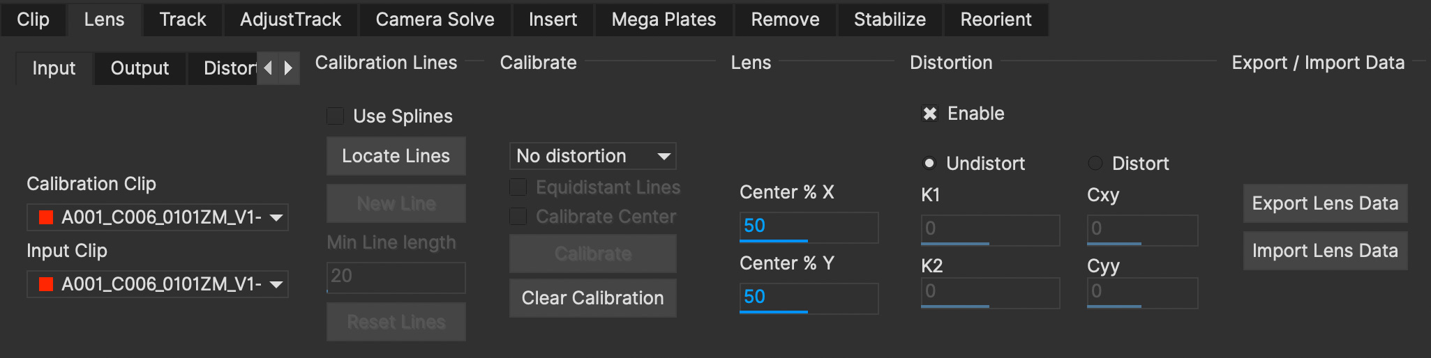
Input tab
Here you have two options:
The Calibration Clip is the clip used for finding and selecting lines to calibrate with – just select the clip from the pulldown menu if you have imported it or import it by selecting the Import button and using the file browser to locate the file.
The Input Clip is the input for the distort/undistort process – just select the clip you want to distort or undistort from the pulldown menu.
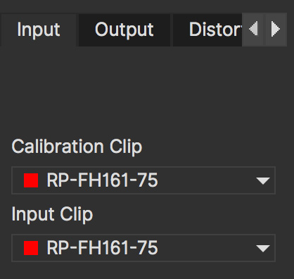
Output tab
This is a way to re-name a distortion setting if you want to have more than one distortion applied. You can choose to leave the input clip intact and create a new clip containing the output from the Lens module, and then rename the rendered distorted or undistorted file and carry on working. Just select the clip from the pulldown menu and select the New… button to name the new clip. The new clip will be the same as the current output if you choose to select that it inherits the attributes of that output clip.
Distortion Map tab
Here you have two options:
The Undistort (Inverse) is the distortion map clip used to set Undistortion for the input clip
The Distort (Direct) is the distortion map clip used to set distortion for the input clip

Calibration Lines
Line calibration is the most important part of the process for 1-parameter, 2 parameter and Anamorphic calibration: These buttons work to locate and then define the straight lines in your shot. See below.
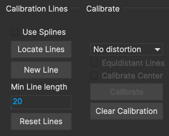
Use Splines
Turn this option on if you want to draw layer splines to calibrate the lens.
When this option is in use, any splines you draw in the viewport will be open splines, allowing you to define curves in the scene more easily than the line detection method.
The workflow is as follows:
Turn on "Use Splines" in the Lens module
Select the X-Spline tool
Draw lines that exactly follow any curves in the footage that should be straight when calibrated.
It’s best to draw enough splines that define the curve of the lens on all sides of the shot.
They should reach as close to the outer edge as possible as that helps define the maximum distortion.Select a Calibration type (see "Calibrate Parameters" below)
Click Calibrate
Below is an example of splines drawn on the edges of a building shot with a wide angle lens: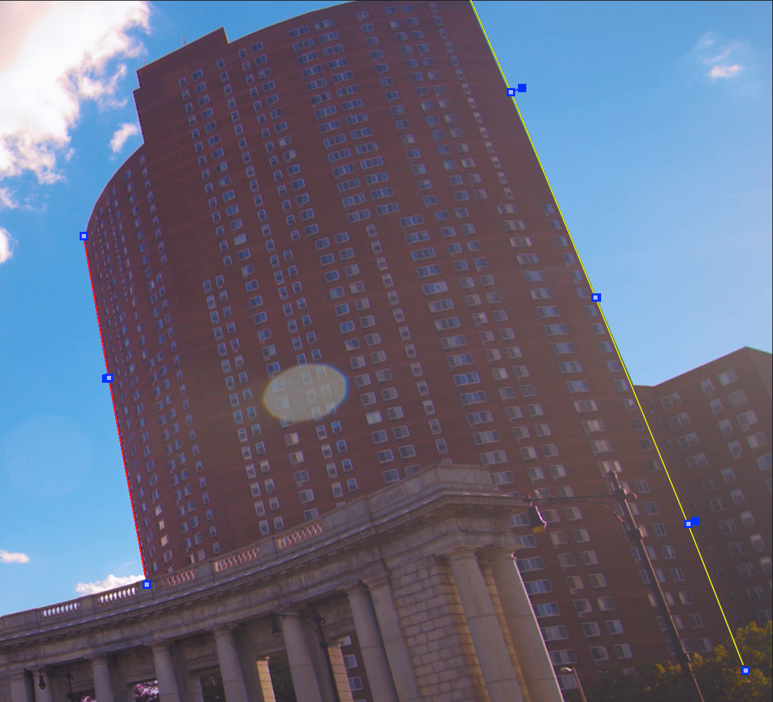
In order to use a spline in the layer list, its processing cog must be turned on. The cog is on by default when you draw a new layer.
Locate Lines
Select the Locate Lines button once for the image you want to use for calibration.
The output of the Locate Lines process is an overlay showing all the line segments that were detected in the image. Typically longer lines will be divided into two or more line segments. See "Min Line Length" below.
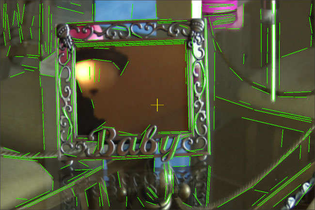
New Line
Using the New Line button you can start selecting line segments to define the straight lines in your scene.
To select which lines you want to use for calibrating the distortion, select the New Line button each time you want to select an entirely new line.
Select one or more line segments lying on the same line in the scene by placing the cursor over each segment and selecting them.
As you hover over the lines the currently closest line will be highlighted in red to indicate which line will be selected.
As you add more segments, the completed line is rendered so that you can check for mistakes. Each line you select will be colored differently to clarify the groupings of the line segments.
Try to choose lines that exhibit the most distortion, typically those reaching towards the edge of the image, and not pointing towards the center .
Try also to achieve good coverage of the whole image, because otherwise the distortion may only be computed correctly in the part of the image where the lines are chosen. If you select a line segment incorrectly, click on it again to deselect it.
It is important to remember to select New Line each time you want to select the segments of a new line in the scene.
Min Line Length
Increase the Min Line Length parameter to show only longer lines and simplify the display, or if you only short line details, try a smaller line value.
Calibrate Parameters
Having chosen your lines (see above), you need to select a camera model:
If only a small amount of distortion is present in the images, choose the 1-Parameter radial distortion model. Then press the Calibrate button. This will find the optimal value for the radial distortion parameter to straighten the selected lines.
You can use the 2-Parameter radial distortion model if the 1-Parameter model doesn’t capture all the distortion in the image. This distortion model is often used when there is a wave or irregularity in the lens.
Anamorphic can be used for any lens with Anamorphic or different vertical and horizontal distortion.
Distortion Map is only used with Distortion Maps and is not related to line-selection based calibration (see below)
Equirectangular will automatically set and calibrate the lens to standard Equirectangular lens format and needs no further calibration. See the Equirectangular Lens Workflow with 360 VR section above for more details.
The Grid display option will show a reference grid with the computed distortion added.
Here is an example grid of a 1-Parameter distortion model:
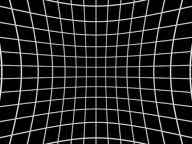
Here is an example grid of a 2-Parameter distortion model:

Here is an example grid of an anamorphic distortion model:

Calibrate button
Once you have selected your lines and set either the 1-Parameter, 2-Parameter or Anamorphic models, you can click this button to start computing the calibration. This will invoke the Mocha Pro camera calibration algorithm which will apply the new calibration parameters to any image you are working on in the current project.
The No Distortion parameter does not compute any distortion and the 1- Parameter Inv model is only for use with RealViz Rz3 files.
If you have a grid image, select the Equidistant Lines box and then select lines appropriately for a grid as explained above.
Note: You only need to render the image and remove the computed distortion if you want to save the output – Mocha Pro will use the calibration data generated without having to use an undistorted clip. To render the clip use the Distort/Undistort controls.

Lens
The image center is naturally set at the center of the image by default. Again the coordinates can be entered manually if you want to eye match the center position of the lens by dragging the Center %X or Center %Y sliders or highlighting the current value and typing in a new value. Alternatively, switch on the Calibrate option so that it will be adjusted automatically when you invoke the camera calibration algorithm.
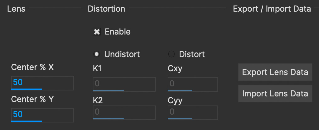
Distortion
The distortion values for the current camera model can be entered manually if you want to match the lens distortion by eye, or they can be computed automatically using the Calibrate button – which is considerably quicker and easier. To adjust manually simply drag the sliders to increase or decrease the values in the K1/Cxx, K2/Cyx, Cxy & Cyy fields or highlight the current value and type in a new value.
Enable
This checkbox Enables the calibration lens distortion for the scene.
Select whether when you render an image you want to remove or add distortion here by selecting the Undistort radio button to remove distortion or the Distort radio button to add distortion.
Distort/Undistort
These buttons are for rendering the clip with the distortion or undistortion values selected.
K1/K2/Cxy/Cyy
These fields define the exact numerical values for the calibrated distortion.
If your calibration doesn’t look quite right, you can adjust these fields to modify the result.
Exporting
Export Lens Data
You can export the lens parameters to a variety of formats. See "Exporting Lens Data" below for more information:
Mocha Lens for After Effects: This format is used exclusively with the Mocha Lens plugin for After Effects, which you can download separately from the Boris FX Website.
Distortion Map: A renderable Distortion map to use in supported applications, such as Nuke.
Mocha XML Lens Data: You can export the lens parameters in a simple XML file format by selecting the
Export Lens Data…button.
This can be used to import into future Mocha projects so you don’t need to recalibrate the same lens.
The parameters are written in a resolution-independent way. The focal distance and image center x/y are represented as multiples of the image width and height. The distortion parameters are written directly.
Import Lens Data
Here you can import Mocha XML Lens Data to define pre-calibrated lenses.
When imported, the K1, K2, Cxx and Cyy fields are populated and the calibration type is set, ready for use.
Rendering lens distortion
Once you have a calibrated lens, you can render using the timeline controls:
Selecting the right arrow renders the clip forward from the current point in time.
Selecting the left arrow renders the clip backwards from the current point in time.
Selecting the central button with a square stops Mocha Pro from rendering, which can also be done by selecting the escape or space keys on the keyboard instead.
Selecting the cog render button just renders the single frame at the current point in time. This is useful for testing a single frame before deciding to render an entire sequence.
Using Grid Images
A common way to generate accurate distortion models is to take an image of a calibration grid, which not only provides long straight lines that exhibit the distortion clearly, but also restricts the lines to a rectilinear grid. The latter constraint can be used to improve on the simple "straightening lines" technique.
If you are using a grid image, select the Equidistant Lines
button. This will enforce a regular grid structure on the selected lines, by forcing the distance between adjacent horizontal and vertical lines to be a constant fixed value.
To use this feature, select lines a fixed distance apart on the grid. You can use a different separation horizontally and vertically. You don’t have to select the lines in the right order - Mocha Pro will re-order the lines according to their horizontal and vertical position on the image.
You also don’t have to select all the grid lines. All that matters is that the distances on the grid between adjacent sampled horizontal lines are the same, with the same rule applying vertically as well.

Grid image with sampled equidistant horizontal and vertical lines. Image courtesy of Jean-Yves Guillernaut, University of Surrey
Note that when you fit a grid, the Grid display option attaches the rendered grid lines to the image grid, so that you can easily see the result.
Anamorphic Camera Model
In cases where even the radial distortion models are not sufficient, or you have an anamorphic shot for which a radial distortion model is not suitable, select the Anamorphic camera model. This allows for different horizontal and vertical distortion. This is the model used in 3D Equalizer V3, although without the inversion of the model used in that product, and we use the "raw" curvature parameters cxx , cxy , cyx , cyy .
You will probably need a grid image to compute the parameters of this model accurately.
Calibrating the Image Center
The image center is by default set to the center of the frame, i.e. 50% of the frame dimensions in both directions. If the center of distortion is or may be offset from the center of the frame, these values need to be modified.
You can either select the correct image center manually by eye or switch on calibration for the image center , which will then calibrate for the image center along with the distortion parameters. A yellow cross indicates the image center position.
Manual calibration
If you don’t get good results from the Mocha Pro calibration procedure, or you have known distortion parameters that you wish to use in Mocha Pro, you can select the distortion parameters manually.
By manipulating the distortion parameters and observing the effect on the image, choose the parameters that straighten up the curved lines as accurately as possible. This should at least deal with the worst effects of the distortion.
Lens Workflow with Distortion Maps
If you are working with Distortion Maps (sometimes called UV maps or ST Maps), a lot less calibration is required. You can simply bring in your map and it will automatically set the lens.
| Distortion maps need to be 32-bit floating-point component RGBA in order to be read correctly by Mocha. |
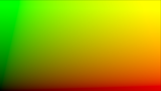
An example of a Distortion Map
Go to the "Distortion Map" tab on the left side of the Lens Module
Use the "Undistort (Inverse)" and "Distort (Direct)" drop downs to import your maps files
Click on the Calibration dropdown and select "Distortion Map"

To check the distortion, turn on your grid
You can now choose to render out the distortion, or use the current calibration to assist your tracking and insertion workflow, as you would a line calibration.
Keep in mind the hard boundaries of the Distortion map being imported may affect the tracking of your shot.
| You cannot export Lens Data with a Distortion Map calibration. You will only be able to perform track and render operations. |
Exporting Lens Data [Mocha Pro Only]
The Lens Module provides different exports for getting your lens data out to other applications.
Mocha Lens for After Effects
This format provides a way to get the Lens data into After Effects via the Mocha Lens for After Effects plugin which you can download and install separately.
Exporting data to After Effects is done via the clipboard, similar to the tracking and shape data methods. To bring data into After Effects:
Click on Export Lens Data in the Lens Module or the File menu
Select "Mocha Lens for After Effects" in the drop down
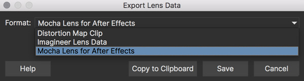
Click "Copy to Clipboard"
Switch to After Effects
Select the layer you wish to add the effect to
Press CMD/Ctrl+V to paste the data
A lens effect will then be created in the layer with parameters from Mocha. You can choose to Remove Distortion or Add Distortion from the Effects panel.

Distortion Maps
| Distortion maps feature in the Lens Module only relate to Mocha Pro and are not available in Mocha HitFilm or Mocha AE |
This format will render a map for programs that support color-based displacement or distortion (such as UV or STMaps). This is also useful if you want to save a calibration so it can be used on another shot, by importing the Distortion Map back into Mocha.
By default the Distortion Map will only render 1 frame, unless you have an animated distortion calibrated in Mocha.
Distortion Maps may also generate a map larger than your footage dimensions in order to accommodate overscan of the distortion.
| Distortion Maps exported from Mocha are primarily focused on calibration inside Mocha and Nuke. Third-party plugins or programs like Fusion and Flame may interpret the maps differently and you will need to adjust them accordingly. |
Click on Export Lens Data in the Lens Module or the File menu
Select "Distortion Map Clip" in the drop down
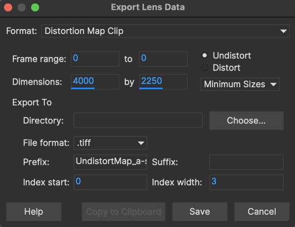
Choose whether you want to render a map to Undistort or Distort with the radio buttons on the right
Choose the size of map you want to render from the dropdown underneath the radio buttons:
Minimum Sizes: This will render distortion maps at the minimum size possible to maintain correct distortion. The Undistort and Distort maps may vary in size to accomodate for overscan.
Equal Sizes: This will render the Undistort and Distort maps at equal dimensions to make 1-to-1 mapping easier. Dimensions will be based on the larger of the two map sizes calculated.
Choose a destination folder for the image
Distortion maps must be 32 bit floats, so TIF or DPX will be the best options
Click "Save"
Load the Distortion Map into the program of your choice
|
Using Tracking Data Exports with Lens [Mocha Pro Only]
Using Tracking Data Exports with Undistorted Shots
If you have undistorted a shot and plan to export tracking data to the result, you will need to check "Remove lens distortion" in the tracking data export dialog in order to match the undistorted data.
![]()
This will make sure the tracking information is set to fit the same flattened information you are using elsewhere.
Using Tracking Data Exports with Distorted Shots in After Effects
| Equirectangular Lens Distortion does not currently support After Effects Lens data export. |
If you want to keep a shot distorted and plan to export tracking data, you will also need to check "Remove lens distortion" in the tracking data export dialog and then apply the lens distortion to the result in After Effects.
Because of the way After Effects handles render order, you need to do a few extra steps to get a corner pin working correctly:
Click on Export Tracking Data… in the Track Module or the File menu.
Select your format and select the "Remove lens distortion" checkbox.
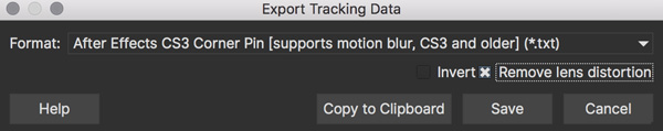
Click "Copy to Clipboard".
Switch to After Effects.
Make sure your insert layer is the same size as the source comp. If not:
Precompose the layer and move all attributes into the new composition.
Open the Precomp and fit the layer to the composition dimensions (Layer | Transform | Fit to Comp).
Paste the tracking data you exported on the clipboard to the insert layer. You will notice that it will probably not be sitting in the right spot. This is normal.
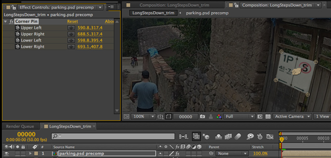
In order to apply the lens distortion to the insert layer correctly, you now need to Precompose the layer to make it fit the same dimensions as the original source.

You can now go back to Mocha and export the Mocha Lens for After Effects data.
Paste the lens data you exported on the clipboard to the Precomposed insert layer.
Choose "Apply Distortion" from the drop down in the effect.
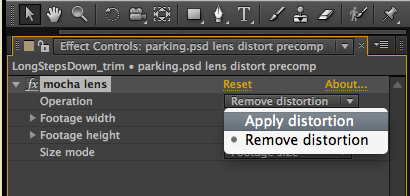
If you notice your insert is clipping, this may be because the precomposed layer is going past the boundaries of the pre-composition. You can fix this by opening the precomp and making it larger:
Open the Lens-Distorted Precomp
Open Composition Settings
Increase the dimensions of the Composition. For example with a 1920x1080 shot with large distortion try adjusting the width to 2500.
Close Composition Settings and go back to your original composition to check the clipping
Tips for Lens Calibration
When working on large files, drop the proxy scale
If you set the proxy scale in View Controls from Full Res to Half Res it should still give enough information to locate good lines, and will be a lot faster.
Make sure your aspect ratio is correct
Note that for the radial distortion models you need to have selected the correct pixel aspect ratio for the images when you started the project. If you have chosen the correct aspect ratio the image will appear in the correct proportions on the screen.
The film back width and height selected when you started the project determine the pixel aspect ratio. Mocha Pro will normally select the correct film back from the image dimensions, but sometimes it may be necessary to make manual adjustments if the correct match was not found.
Using Mocha Pro for 360 VR workflow
The Mocha Pro 360 features are specifically designed to work on equirectangular shots.
To use Mocha Pro on a 360 equirectangular shot you need to first set up the 360 image. You can then begin using Mocha just like you would any other footage.
Using Equirectangular footage in Mocha Pro
1. Load Equirectangular footage into Mocha and set the Lens type
The first step for working in 360 VR mode is to import and define you are working in Equirectangular space.
Mocha Pro can set this in the New Project dialog on standalone:
Or in the Views drop down in the plugin:
You can also change to Equirectangular in the Lens module:
Go to the Lens module
In the “Calibrate” section, choose “Equirectangular” from the drop down.
| VR footage with an odd pixel width may not wrap correctly and you could see artifacts. |
And that’s it! You’re now ready to work in VR lens space. If at any time you want to adjust the 360 view numerically, the fields Longitude, Latitude and Field of View are available to adjust in the Lens page.
2. Switch to the Track module and view your footage in 360 mode
As soon as you have set the Equirectangular lens type, a new “360” button will appear in the view controls. Switch over to the Track module and click on this button to immediately jump to 360 Rectilinear space.

If you press and hold the 360 button, you can also jump to a specific 360 view, such as Zenith, Nadir, Front, etc.
To navigate in the 360 view:
The Pan tool (X by default) pans the view in all directions
The Zoom tool (Z by default) changes the Field of View (FOV). You can reset the FOV in the Lens module
You can change the Pan and Zoom shortcut keys in preferences.
| Panning and Zooming in 360 mode also updates the Latitude, Longitude and FOV parameters in the Lens module. Panning and Zooming outside of 360 mode just zooms and pans the image as normal. |
3. Draw a layer and start tracking
You can draw layers in either 360 view or Equirectangular mode.
We recommend working in 360 view, as this is the intended workflow and is much more natural because you don’t have to consider seams or poles.
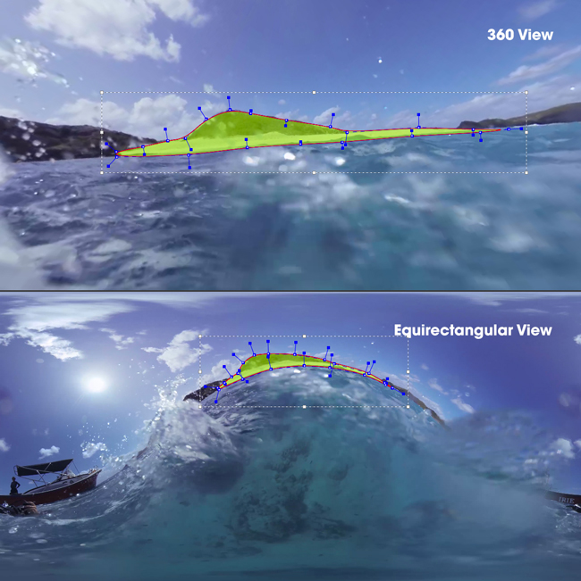
See the Tracking Basics chapter for more details on how to set up layers for optimal tracking.
(Images courtesy of Makoto Hirose, SeaPics Japan)
4. Rotoscope in 360 mode
Like tracking, we recommend doing all roto in 360 mode. Roto will automatically warp, cross over poles and seams and create seam duplicates to make it easier for rendering and export.
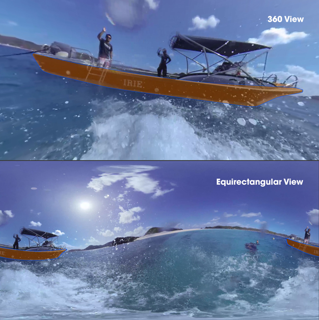
Feathering is also handled in 360 mode using the inner and outer edges.
You can preview the flattened version of the roto at any time by simply toggling off the 360 button.
See the Rotoscoping Basics section for more details on Rotoscoping effectively.
(Images courtesy of Makoto Hirose, SeaPics Japan)
5. Work in Insert, Remove and Reorient modules
The Insert module and Remove module work exactly like regular Mocha Pro. See their respective chapters in the user guide for more details.
You still draw the layers and set up renders in the same way, and they are rendered across the 360 seams correctly.
For Reorienting and stabilzing the horizon of a VR shot, you will need to use the Reorient module, which is only available when your project is set to work with 360 footage.
See Mocha Pro: The Reorient Module for more details on how to Reorient a VR shot.
See other relevant module sections of this user guide for more details on each module use.
| The Camera Solve and Stabilize module are presently unsupported in VR mode. |
6. Render and Export
Rendering
Renders work in the same way as they do in the standard Mocha Pro workflow. You can either render them to file, or render via the plugin host.
You can render the current 360 view from the Lens tab, as panning and zooming in 360 mode is a lens calibration. In the standalone, this is controlled via the Lens tab.
In the plugin, you can control and render the lens directly from the Mocha Pro plugin interface. See Mocha Pro Lens Plugin Rendering Workflow for 360 VR below for more details.
For everything else, such as Remove and Insert, renders are rendered into Equirectangular space.
Exporting
Currently export of tracking data is unsupported. Tracking data will paste to the correct location in your equirectangular view,
but will not be corrected for Lens distortion due to most editors and compositors not correctly supporting pole or seam splitting of tracking data.
It is best to use the Insert module render process to get what tracking data you need out of Mocha.
Shape export data presently exports as duplicate splines. This means that any roto shape that crosses the seam will automatically be duplicated into two separate splines on either side of the Equirectangular view.
Split VR shape data is presently supported for:
After Effects and Premiere shapes
Nuke Roto and RotoPaint
SSF
For other compositors and editors you can either use the matte rendering in the Mocha Pro plugin, or render matte clips from Mocha directly.
See Using the Mocha Pro Plugin for more details on controlling mattes in the plugin interface and Exporting Rendered Shapes for how to render mattes to file.
Mocha Pro Plugin Lens Rendering Workflow for 360 VR
You can use the Lens: Undistort and Lens: Distort options in Mocha Pro Plugin to render out 360 patches for easier paint and effect work back in the host.
The patch workflow is a one-way control system in the plugin interface independent of the Mocha GUI, which means you don’t need to open Mocha to control the lens view.

By choosing Lens: Undistort from the render options in the plugin, you can then control the view by adjusting three controls:
VR Lens Latitude
VR Lens Longitude
VR Lens FOV
Alternatively you can pick a view using the Views dropdown option.
This replicates the 360 views in the Mocha GUI, allowing you to choose between specific angles such as Zenith, Nadir, Front, etc.
The lens distortion workflow for the plugin is:
Click Render in the 'Module Renders' section of the plugin interface and choose Lens: Undistort from the 'Module' drop down. You should see the view change to a rendered 360 view.
If you don’t see the view change after choosing Lens: Undistort:
Open the Mocha GUI and set your footage to Equirectangular mode in the Lens module.
Close and save Mocha
Set your view using the VR lens parameters in the plugin interface
Copy the current Mocha effect
If necessary, Nest/precomp the rendered lens patch. You must precomp in After Effects for the next steps to work correctly.
Paste the original effect back on top of the nested comp.
Choose Lens: Distort from the 'Module' drop down in the pasted effect to restore the warp back to its original position
Merge/layer the final result back on top of your original footage.
You can then perform any paint or effect work on the lens-distorted version of the footage and it will be re-distorted correctly on top of the original footage.
The Reorient Module
| This section applies specifically to Equirectangular 360 VR footage |
To use the Reorient module on a 360 equirectangular shot you need to first set up the 360 image.
See the Using Mocha Pro for 360 workflow section for details on how to set up and work in a 360 shot.
Reorienting Equirectangular Footage in Mocha Pro
The Mocha Pro Reorient Module provides two useful tools for adjusting the VR camera:
The ability to track and stabilize the VR horizon in each rotational axis
The ability to control the position of the VR horizon in tilt in each rotational axis
1. Track Horizon or Track Near-Objects
Horizon Tracking
The most efficient way to stabilize and reorient is to track a layer (or series of layers) near the horizon.
It doesn’t have to be exactly on the horizon, but it helps to be as close as possible. Multiple layers in sequence will concatenate for a single solution (see below).
| Mocha assumes that if you are tracking with more than one layer at a time that you’re using a near-object track. See "Near Object Tracking" below. |
Near-Object Tracking
From Mocha version 5.6.0 onwards, if you do not have an obvious horizon to track or it is constantly obscured,
the next best option is to use a series of layers closer to the camera.
You will need at least two layers that are non-coplanar, which is a fancy way of saying "Not on the same plane".
This is necessary for the Reorient module to work out the relative motion between the planes and calculate a smooth result.
For example, if you are trying to reorient a scene with a corridor, tracking one wall is not enough:
You will need to also track the opposite (non-coplanar) wall or the floor/ceiling to get the near-object depth for mocha to understand the movement of the scene.
A Mix of Near-object and Horizon Tracking
If you have a long shot where you can see the horizon in parts and not in others you can track both the horizon and near objects in sequence.
Mocha will assume that a single layer is tracking the horizon and multiple layers on the same frames are tracking near-objects.
For example, you can track the ground plane and a wall plane and they are on different planes.
Tracking Long or Rapidly Changing Shots
If a shot is moving very far, or has a lot of changes (such as moving through trees), you can concatenate tracked layers together.
However, it is important to make sure there is a little overlap between the tracked layers in order to blend the tracked layers together, for example:
Layer 1: Tracked from frame 0 to frame 100
Layer 2: Tracked from frame 90 to frame 280
Layer 3: Tracked from frame 265 to 400
Etc.
This helps to smooth any jumps from one tracked layer to the next.
2. Adjusting the Horizon
Like most modules in Mocha, to use the Reorient module stabilization you first need a tracked layer.
Track a layer(s) for the stabilization (see step 1 above!)
Move to the Reorient module. This will turn on the 'View Horizon' checkbox, which shows the red horizon line on screen. It will also disable Preview so you can work with the original clip.
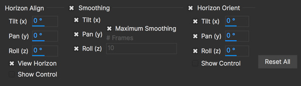 +
+Adjust the red horizon line to fit your horizon using the column “Horizon Align”. You can do this in either 360 mode or in Equirectangular mode. We recommend Equirectangular mode, as it is much easier to see the whole horizon.
If you would prefer a visual control, you can turn on “Show Control” under the Horizon Align rotation fields:
Move up and down to control tilt
Left and right to control pan
Rotating the circle controls roll.
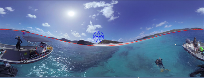 +
+
Once your line fits the horizon, you can turn off the 'View Horizon' check box.
If 'Preview' doesn’t turn on immediately, you can toggle it in the view controls. The button is to the left of the 360 icon in the view controls.
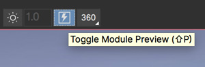
3. Smoothing the Horizon
You can control the Smoothing to any rotational axis by turning off the tilt, roll and pan controls.
For example, if you’re only interested in stopping the camera from panning, you can just leave “Pan” on.
If you don’t want to lock the smoothing completely, you can turn off “Maximum Smoothing” and adjust the number of frames to stabilize the horizon jitter.
4. Reorienting the Horizon
Finally, if you want to position the camera exactly, you can do so by using the ‘Horizon Reorient’ column.
This has exactly the same parameters as the Horizon Adjust column, allowing you to either move the camera via the fields, or via the on-screen control.
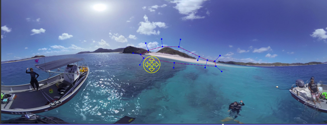
If you have the Preview button turned on, it will update in the view automatically.
5. Rendering
Like all modules, you can choose to either render in the Mocha GUI, or choose “Reorient” from the render options in the main plugin interface back in the host.
(Footage images courtesy of Makoto Hirose, SeaPics Japan)
Graphs
The Graphs in Mocha let you view and manipulate keyframe data.
There are two types:
The Dope Sheet: For easily moving, copying and deleting keys
The Curve Editor: For viewing curves of animation and editing values
The Graphs panel is located on a side tab to the left of the parameters.
You can switch between the Dope Sheet and the Curve Editor inside the Graphs panel by toggling the buttons on the far right of the panel.

The Dope Sheet
The Dope Sheet is used to move, copy and paste keyframes in your layers.
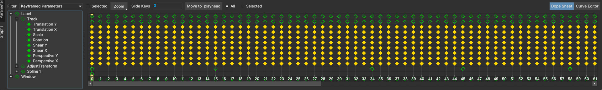
Navigating the Dope Sheet
You can navigate the Dope Sheet space by using the scroll bars horizontally and vertically.
Holding CTRL/CMD+Scrolling the mouse wheel will let you scale up and down the timeline.
You can also zoom to specific ranges by selecting one of the options from the "Zoom" drop down at the top of the Dope Sheet view:

Group Keyframes vs Parameter Keyframes
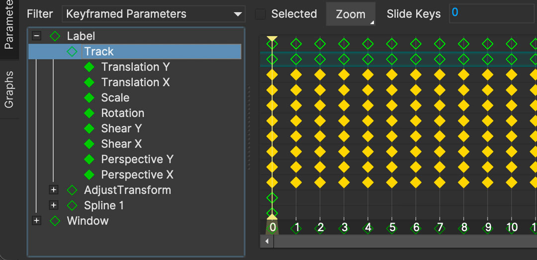
As you create animation or tracking data, you will see a number of hollow keyframes appear in the Dope Sheet. These are known as Group Keyframes which are keys that contain multiple sets of Parameter Keyframes underneath them.
You can move the Group Keyframes like normal animation keyframes, but instead of a single animation key, they will move all the keyframes underneath them.
This is useful when you need to shift a whole section of animation in a layer, and not just an individual point or parameter.
Expanding a section of the layer tree in the dope sheet will reveal either Parameter Keyframes or more Group Keyframes, depending on how many levels in that layer tree there are.
Hidden keyframes in groups
Some keyframes are hidden as they take up a lot of space.
An example of this is PowerMesh tracking keyframes, which are very numerous and impractical to reveal in the Dope Sheet.
When a hidden keyframe exists in the timeline, the group-level keyframe will still show, letting you know there is data that can be moved or manipulated.
Selecting and Moving Keys
To select keyframes, you either click on one of them in the Dope Sheet, or marquee select a section. You can use SHIFT to pick multiple keys.
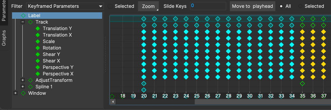
You can move the keyframes manually by dragging them with the mouse, or you can use the standard Copy/Paste keys (CTRL/CMD+C, CTRL/CMD+V) to copy keys and paste them at the current playhead position.
| At this time you cannot copy and paste Group Keyframes, only Parameter/Animation keyframes. |
Sliding Keys
To move all keyframes in the project up or down the timeline to accomodate frame offsets or new clip lengths, you can use "Slide Keys".
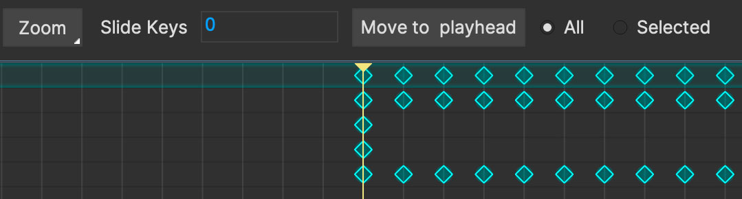
You can slide keyframes one of two ways:
Enter the keyframe position you want into the Slide Keys field and press enter
Select the "Move to playhead" button to push the keyframes to the current playhead position.
If you need to only move some of the keyframes, just select the ones needed and use the "Selected" radio button option before performing the slide.
The Curve Editor
The curve editor provides a way to preview the flow of data and modify parameter keyframe values.

Viewing keyframe data
Clicking on a parameter in the curve editor view will show its keyframes and curves if it has any data.
Parameters with keyframe data are highlighted with keyframe icons in the left tree.
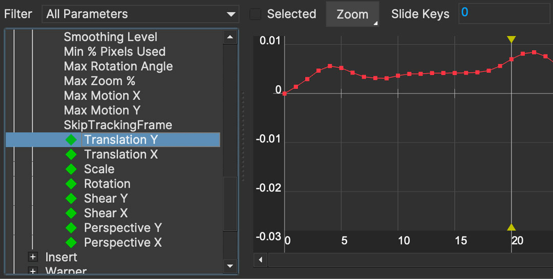
The most common three data types you will be looking at are:
Tracking data
Spline Control Point data
Camera Solve data
Parameters with single keyframes are also highlighted.
Previewing Linked Track and AdjustTrack Data
Layers that are linked to a separate layer’s track data will show in the parameter data as a ghost curve with no keyframes. You should modify the data from the linked layer.
Layers with AdjustTrack data will show how the track is modified when selecting any tracking data parameter.

As you adjust points in the AdjustTrack module, the magenta curve will update to show the changes.
Navigating the Curve Editor View
You can navigate the Curve Editor space by using the same pan and zoom controls you use in the viewer, either by using the middle mouse button and scroll-wheel of your mouse for panning and zooming respectively, or using the X key to pan with the left mouse button.
You can also zoom to specific ranges by selecting one of the options from the "Zoom" drop down at the top of the Curve Editor view:
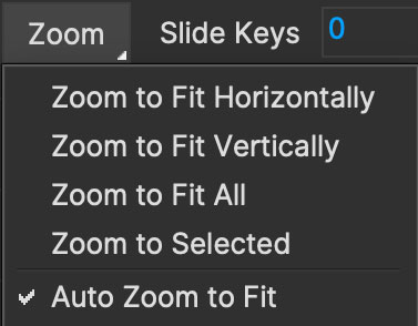
Zoom to Fit Horizontally: Scales the keyframe data curve to fit the time range currently being viewed
Zoom to Fit Vertically: Scales the keyframe data curve to fit all values
Zoom to Fit All: Scales both vertically and horizontally to fit all data to the view.
Zoom to Selected: Scales vertically and horizontally to fit the view for just the selected keyframes
Auto Zoom to Fit: A checkable option, this automatically fits all data inside the view when selecting a parameter.
Adjusting values
Any selectable keyframe on a curve can be adjusted and you can adjust multiple keyframes at once. You will be given the offset for the value as you adjust.
Constant keyframes
All keyframes in Mocha default to linear interpolation. You can right-click any keyframe to set a hold keyframe by choosing "Constant" from the interpolation menu:
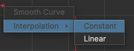
This will be represented by a squared-off curve in the view.
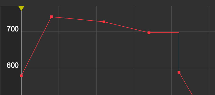
Smoothing Values
If you want to bring a set of keys in line with the curve of surrounding keys, you can right click a selected set of keyframes and choose Smooth Curve.
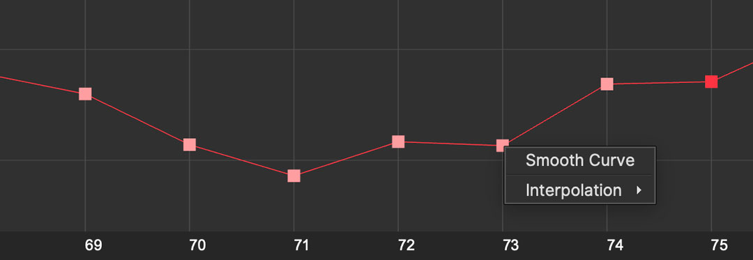
The keys will then be smoothed along the curve:
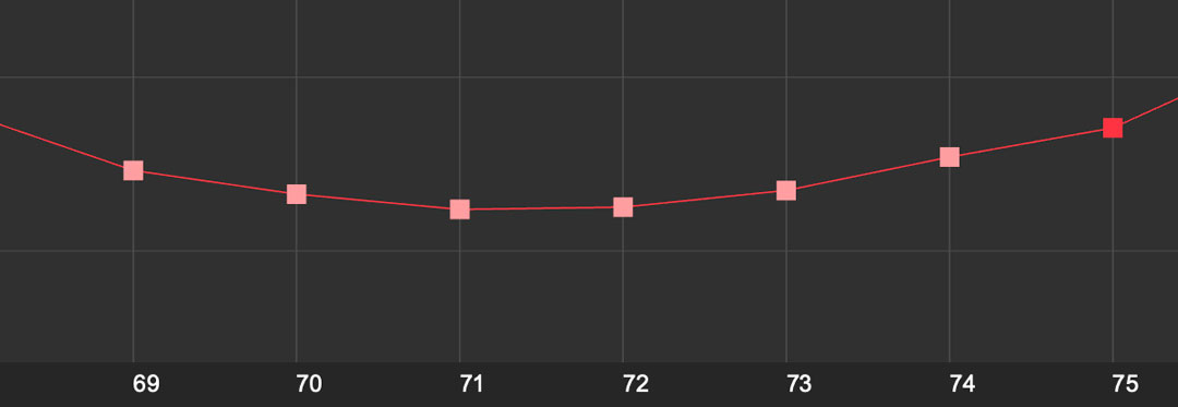
Filtering Keys
Keyframe markers
Parameter groups that have keyframe data in the project are marked by a hollow keyframes in the lefthand data tree.
Parameters with keyframe data are similarly marked with a regular keyframe icon.
This makes it easy to see which parameters can be clicked to view their curve information or keys.
View Keyframed Parameters Only
The default filter for viewing keys in Graphs is Keyframed Parameters, which hides any parameters that do not have keyframes.
You can change the filter in the top left of the Graphs panel.

View selected only
You can reduce the amount of data in the dope sheet and the curve editor by using the Selected checkbox near the lefthand parameter tree.
When selected is on, only selected groups, layers or spline control points will be visible in the graphs.
The Clip Module
Managing clips
You can import any number of clips into the project. Much like a compositing application, you can have a multitude of assets in the application you may wish to work with at any given time. As clips are imported into the project, they populate Clip list drop-down menus found throughout the application.

Above is shown a list of clips that have been loaded into a project.
You can also add additional footage streams to each clip in Mocha Pro using the Add… button.
Importing New Clips
The first clip is always imported when you start a new project, and the location of the clip’s footage stream is shown in the Footage Streams section to the right.
The first clip you start with establishes the aspect ratio and resolution for that project. This can be adjusted in the clip tab.
Additional clips can be imported into the project through the Clip tab.

The clips should match the original project clip ratio set for the project (the dimensions of the first clip you imported when you started the project). You can choose the "inherit attributes" drop down to match the original project clip settings.
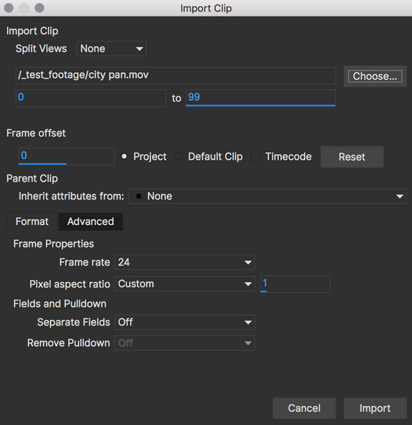
Clip and Footage Stream Workflow
The Clip tab handles multiple footage streams in a single Mocha clip.
Clips consist of a container and one or more footage streams. Clips can contain any number of footage streams, which you can then map to a view if required.
Most commonly you will only be working with one footage stream, which is mapped to the Mono view. If you are working in stereo (Mocha Pro only) you will have multiple views.
If you import multiple footage streams into the same clip, you can use the View Mapping dropdown to change which footage stream is shown.
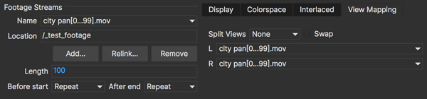
If you are dealing with multi-channel clips such as EXR files, all views are loaded automatically.
If you are working with individual views (TIF, DPX, JPG etc), you can import the additional footage streams using the Add… button under the Footage Streams dropdown (Mocha Pro only).
Importing New Footage Streams to an existing Clip
| This feature is only available in Mocha Pro. |
If you want to import additional footage streams in Mocha Pro, you can do so using the Import button under the Footage Streams dropdown.
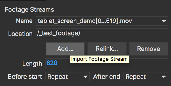
You can then choose a new footage stream to add to the current clip from the Import dialog.

Removing Clips
You may clean up the project by deleting clips you no longer need. Select the clip in the clip drop-down list and hit Delete. That clip will be removed from the project.
Relinking Clips
When moving project files or updating footage, you may need to relocate the footage on your system. To do this:
Select the clip you need to relink from the clip drop-down list
In the Footage Streams section of your clip, choose the footage stream you want to relink. Most commonly for non-stereo projects there will only be one clip stream.
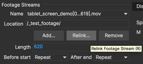
You will be presented with a relink dialog. Click the Choose… button to browse for a new clip you wish the original to be replaced by.
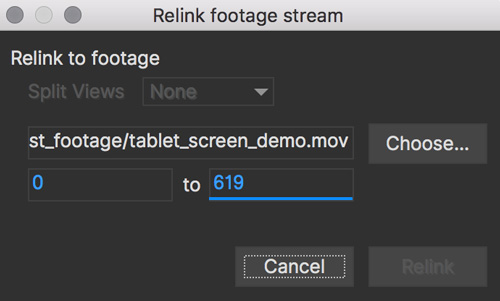
Make sure an imported footage stream has the same aspect ratio as the original project clip. You can conform your relinked clip to the current settings in the project, or keep them the same.
Selecting a Clip to Track
Most often, the first clip you imported will be the one you wish to track. There are times when you may get an updated shot with color correction or some other enhancements to make tracking easier. To use this new clip, you must first import it into the project as described above.
To select to track on this new clip, you must choose it in the Track tab’s Input drop-down.
| An imported clip must have inherited attributes from the original base clip to become trackable. See "Importing Clips" above. |
Selecting a Clip to Rotoscope
Rotoscoping can be done on any of the clips you have imported. To change the clip you are viewing in the canvas, select the clip in the View Controls drop-down list. You will notice that any clip you’ve imported into the project will appear here.
| An imported clip must have inherited attributes from the original base clip to be able to roto correctly. See "Importing Clips" above. |
Keyboard Shortcuts
Keyboard Shortcut customization
You can now customize keyboard shortcuts for almost every tool, action and menu item in Mocha.
Directly, via File | Keyboard | Customize…
By going to Mocha Preferences and clicking the Key Shortcuts tab.
You can create a new profile by duplicating a default profile, then customize the keys. These profiles are then available from the Keyboard menu:
Duplicate one of the default profiles and rename it
Select a category and choose an action you want to change or add a key sequence to
Click in the "Shortcut" column
Enter your key sequence
Click anywhere outside of the entry cell to complete
Click "Default" if you want to revert your change back to the default shortcut

| Pressing return or delete/backspace counts as a key entry, so please click outside the cell to complete the entry and use the "Clear" button to clear an entry. |
Default Mocha Shortcuts
Below are some of the common default shortcuts for Mocha
Tools
CTRL/CMD + F | Enable Picker tool |
I | Toggle insert point mode on/off |
Z | Enable Zoom tool while pressed |
X | Enable Pan tool while pressed |
CTRL/CMD + L | Enable X spline tool |
CTRL/CMD + B | Enable Bezier spline tool |
CTRL/CMD + Click | Break Bezier handle |
CTRL/CMD + Z | Undo |
CTRL/CMD + SHIFT + Z | Redo |
C | Close contour |
D | Delete point |
Transform
W | Rotate |
Q | Translate |
E | Scale |
Down Arrow | Nudge Point/Layer down 1 pixel |
Up Arrow | Nudge Point/Layer up 1 pixel |
Left Arrow | Nudge Point/Layer left 1 pixel |
Right Arrow | Nudge Point/Layer right 1 pixel |
SHIFT + Down Arrow | Nudge Point/Layer down 10 pixels |
SHIFT + Up Arrow | Nudge Point/Layer up 10 pixels |
SHIFT + Left Arrow | Nudge Point/Layer left 10 pixels |
SHIFT + Right Arrow | Nudge Point/Layer right 10 pixels |
Viewer Canvas
- | Zoom out |
+ | Zoom in |
/ | Zoom to 100% |
* | Zoom to fit |
Alt + 1 | Show/Hide Mattes |
Alt + 2 | Show/Hide Color Layer Mattes |
Alt + 4 | Show/Hide Layers |
Alt + 5 | Show/Hide Spline Tangents |
Alt + 6 | Show/Hide Surface |
Alt + 7 | Show/Hide Grid |
Alt + 8 | Show/Hide Zoom Windows |
` (Back dash) | Show/Hide All Overlays |
Timeline
Alt + Left Arrow | Go to start of clip |
CTRL/CMD + Left Arrow | Go to previous frame |
CTRL/CMD + Right Arrow | Go to next frame |
Alt + Right Arrow | Go to end of clip |
ESC | Stop processing |
Space | Start/stop playback |
Alt + Down Arrow | Set in-point |
Alt + Up Arrow | Set out-point |
Alt+Shift+J | Select current frame field |
Preferences
| Some of the preferences below relate to Mocha Pro. Some preferences may not be available in the Mocha Pro Plugin, Mocha AE and Mocha HitFilm. |
Preferences set the defaults for the main processes in Mocha.
Preferences Crossover
On a new installation you will be asked if you want to port over your existing settings. If you select "Yes", any preferences
from your previous installation of Mocha will be set in the current version. If you select "No" you will not be asked again.
Preferences location
Preferences are accessed through File > Preferences on Windows or Linux (Mocha Pro only) and Application Menu > Preferences on OS X.
Preferences are not changed until you click the OK button.
In some cases you will need to restart the Mocha application for preferences to take effect.
You can also choose to reset all preferences back to the default using the "Restore Defaults" button in the bottom left of the dialog.
Output Settings
File Storage
Output Directory (Standalone only)
The Output Directory settings specify the default location of the directory in which the project file and rendered clips are stored. There is a choice between:
Relative Path: The project directory is a subdirectory of the directory containing the original project clip. By default, the subdirectory is Results. If you often load your project clip over a network, it would be best not to choose Relative Path, because the performance of project and clip I/O will not be as fast as the local disk.
Absolute Path: The project directory as an absolute path. For the best performance choose a folder on a fast disk, with plenty of disk space available.
Autosave
The Autosave box is selected by default. This will automatically save the project you are working on.
Set the interval between saves by increasing or decreasing the value in the Interval (minutes) box.
The default is 5 minutes. If Save Images Every Frame is checked, rendered frames are saved to disk as soon as they are created in memory; otherwise the render to disk only occurs when rendering a sequence of frames.
You can define the Autosave directory or leave it to the system default.
In the standalone, if there is an autosave file available for the project you have loaded, a dialog will appear asking if you want to open that instead.
In the plugin, the dialog will appear if there is an autosave available for a Mocha project done in that host. You can then choose to open, save or remove the project file.
For example, if you are working in After Effects and there is a problem, recovering your AE project and opening the Mocha GUI will show a Mocha Autosave recovery dialog for the project made in After Effects.
If you have other autosaves (for example from another Mocha Pro plugin host), the recovery dialog will NOT appear, as it was a project made in another program.
An example autosave file is called:
"mochaAE_plugin-6_aftereffects-16.mocha.autosave"
This literally translates to: "Mocha AE Plugin project saved in After Effects v16".
In standalone, Autosave is per-project, i.e it will be directly related to the project you are working on. This is because we work with a 1-to-1 match of the project file name.
In the plugin, we can only save an autosave file per HOST, that is, we have no knowledge of the project/layer that is being worked on, so we can only save based on what we know, i.e the host the mocha project was saved in.
This means that in the plugin, a crash from a previous project will trigger a load prompt in ANY project you open created in the same host. For example:
Create an After Effects project with Mocha
Autosave kicks in
Force quit with mocha still open
Reopen host
Start or open another AE project with Mocha
Open mocha GUI
A Load-Autosave file prompt shows up
We time-stamp the autosave dialog so you can have a better idea of when the file was saved, but if you open the autosave it will replace your existing work.
If your plugin autosave doesn’t automatically prompt to open, you can locate the directory in the support path. By default these are:
Windows:
C:\Users\[username]\AppData\Roaming\BorisFX\AutosavemacOS:
~/Library/Application Support/BorisFX/AutosaveLinux:
~/.config/BorisFX/Autosave
You can then Open or Merge the file into a new or existing project.
Autosave Backups
We also back up each session autosave just in case a previous autosave has a problem or you want to revert back to an older state.
You can define how many backups in the "Number of Backups field" next to the Autosave interval field.
Autosave backups are saved to an "autosave_history" folder relative to the current autosave file.
Cache Directory
Specify here the folder to use for caching image data and storing auto-saved project files. For the best performance, choose a folder on a fast disk with plenty of disk space available. A lot of data is written out in the background while you work, approximately three times as much disk space as the taken up by the original clip will be used.
The Cache Original Clip box (Standalone only) is selected by default. This will cache the original clip to the File Cache when a project is created or opened for a more efficient playback and workflow. It is only necessary to check this if you are getting footage from a slow network.
Disk Space Available
The available space in the given disk drive is shown here.
System
Application
Undo History Size
The Maximum Size of the history is the number of user interactions stored in the undo/redo command list. The limit is used to conserve memory.
Maximum Memory Usage
The Maximum percentage of memory Mocha will attempt to use.
Maximum threads per thread-pool (Advanced)
This feature is to limit the number of threads Mocha will use on multi-core machines.
On a machine with many cores, users may wish to limit the number of threads per thread pool
to prevent Mocha from creating too many threads and potentially crashing.
We recommend turning this feature on if you experience frequent crashes when rendering or tracking on high-core machines.
The default value will be the number of available cores. A value of 16 is a good base value to start from.
ML Frame Caching
How many frames to retain in the Machine Learning cache when releasing memory.
This helps reduce slowdown when rendering some ML operations.
The dropdown has three settings:
Balanced: Slower ML rendering with smaller frame (memory) allocation
Performance (default): Good ML rendering speeds with some memory management
High Performance: Faster ML rendering with large memory allocation.
Track in Mocha AE
Check the box if you want to open Mocha Pro via the "Track in Mocha AE" option inside After Effects, rather than loading the bundled Mocha AE.
UI Look and Feel
Number of Shown Layouts
Set how many layouts you want to appear in the View menu. The default is 3.
Field Controls
You can set either:
Rotation Controls: Adjusts the value in the field by moving the mouse in a circular motion. The larger the circle motion, the more refined the adjustment.
Linear Controls: Drag left or right in the field to adjust the value.
Invert Mouse Wheel
Inverts the motion of when scrolling in a field increases the value or decreases it.
Enable mouse viewer scrolling
Toggles scrolling with the mouse wheel. This is on by default. There are two sub-options:
Mouse Wheel Scrubs Timeline: Sets the mouse wheel to scrub the timeline when the cursor is over the viewer or the timeline.
Mouse Wheel Zooms Viewer: Sets the mouse wheel to zoom in and out of the viewer when the cursor is over the viewer.
If you hover over the timeline, it scrolls the timeline instead.
Tablet pressure sensitivity
Toggles whether Mocha reads tablet pressure sensitivity for tools such as the Area Brush. On by default.
Object Brush Settings
Here you can set whether the Object Brush ROI and Preview settings are on or off by default.
View Preview Matte: On by default
Use Auto ROI: Also on by default.
Layer Settings
Default Colors
Defines the default colors for Splines, Mattes and Points
Default Opacity
Defines the default opacity for mattes
X-Spline Default Weight
Sets the default weight of the x-spline control points
Default Bezier Length
Sets the default normalized length of the bezier tangent handles.
GPU
| Any changes to GPU settings requires a restart of Mocha. For standalone, this is simply closing Mocha and reopening. For the Mocha plugin, you need to restart the host environment to reload the plugin completely. |
Display
Use Vertical Sync
Enable vertical sync in the frame display. We highly recommend you keep this on.
Amount of Texture RAM to Reserve
The amount of memory that you want to be reserved for textures. This determines how many frames can be played back in real-time.
Textured rendering may not be compatible with Microsoft Windows Remote Desktop Connection.
Stereo [Mocha Pro Only]
Here you can enable Active Stereo viewing mode if it is available to you.
Matte Rendering
By default, Mocha will generate matte clips and track mattes by rendering with OpenGL to an offscreen buffer.
If Disable Offscreen Buffers is checked, Mocha will fall back to a software-based matte rendering implementation which is slower and produces lower-quality results, but will work on all hardware.
Most users should not need to use this option.
GPU Processing
This option is on by default and sets the planar tracker to use the graphics card instead of the CPU.
If this option is disabled it means you do not have a supported graphics card for GPU tracking.
OpenCL Device
This option lets you choose the graphics card you want to use for GPU tracking.
By default this is set to Automatic, which attempts to choose the best available option.
Allow unsupported GPUs
This option lets you override the officially supported graphics card list and choose any GPU on your system.
Use this option with care as it may lead to unstable results.
Machine Learning (ML) Processing
Compute Device
This option allows you to set a specific device to compute machine learning operations, such as Matte Assist ML.
Usually it should be left to Automatic, but in some cases you may need to define a specific device.
| Selecting the CPU from Compute Device will process ML tools significantly slower. Intel CPUs on macOS are not supported. Use a GPU or Apple Silicon (M1+) where possible. |
Software Update [Mocha Pro Only]
Settings to check for software updates.
Color
Handles defaults for OCIO color settings. See the OpenColorIO (OCIO) chapter for more details.
Clip
If you are working on a number of shots that share the same clip attributes (the same video standard, frame rate and color space), it can be useful to set a default clip setting. Then you will not have to re-enter the same clip information each time you load a clip.
Defaults
FPS
Sets the default frame rate with a dropdown.
You can enter a custom number if you click inside the dropdown.
Custom PAR
Sets the default Custom option in Pixel Aspect Ratio
Frame Offset controls
Options to set you default timeline as frames or timecode, and set a fixed frame offset.
Output matte clips
Check this option to output matte clips to disk when previewing mattes (this option is only available in the standalone version of Mocha).
Revert in input clip
Check this option to revert to the source clip if there is an unrendered frame displayed in the viewer.
A yellow warning telling you the frame is not rendered will appear over the source frame.
Format
Setting the format defines what results are rendered out to, but also define what your Cleanplate clips will be saved as.
Integer result clip format
What to set you rendering result output to for integer clip formats. Currently the choice is between DPX and TIFF.
Float result clip format
What to set you rendering result output to for float clip formats. Currently the choice is between EXR and TIFF.
Float clips will be generated internally as 32-bit float, increasing the precision of compositing operations but using more memory.
Interlacing
Select the Separate Fields button if you normally use field-based clips.
This will usually consist of a video clip with options for PAL (upper field first, also used for SECAM) or NTSC (lower field first) field ordering. Separate Fields will de-interlace the clip and display both fields. When a clip is rendered, the fields will automatically be interlaced back together again. There is also a 3:2 Pulldown option if you mainly work with 3:2 pulldown material.
Video Files
Read/write using
The footage handling process to use. The default is GStreamer. You also have the option to use QuickTime.
Note that your choice of clip media handler does not affect the opening of image sequences such as TIFF, DPX, EXR and so on.
It also doesn’t affect any host source material being opened from the Mocha Plug-In, but will affect any clip media you import directly from disk.
GStreamer
This is a versatile media handling library for reading in various codecs and footage containers.
GStreamer currently has limited support for writing out of clips. More will be available in later versions.
If you need to render out a clip to disk, we recommend using a lossless sequence such as TIFF or DPX.
QuickTime
Open files using the QuickTime library. This will only open footage that QuickTime can open.
| QuickTime is unsupported on macOS 10.15 and above. QuickTime will not work on systems that don’t have the QuickTime essentials installed. |
You must restart the host or the standalone application for any change to the read/write settings.
Mask
Sets the default clip mask.
Lens [Mocha Pro Only]
Camera Model
Sets the default distortion mode.
3D [Mocha Pro Only]
Here you can customise defaults for the 3D viewer.
Default Colors
Customise the colors for points and meshes in the 3D viewport.
Feature Size
Set the default size for features in the 3D viewport.
Logging
Diagnostic Logging
Enable Diagnostic Logging
This is selected by default. The file generated is useful for Boris FX engineers to diagnose error messages and fix any problems.
You can view the log by selecting View Log from the Help menu. You can also change the location of the Log File from its default.
Verbosity
This dropdown allows you to set the granularity of logging when working with Mocha. The default is "Info" which should provide enough information in most circumstances.
A support team member may ask you to set a more verbose setting in order to help troubleshoot a problem.
The verbosity types are:
Trace: Extremely detailed logging. This should only be set if asked to by support.
Debug: Used for information that may be needed for general troubleshooting.
Info: The standard level of logging. In most cases you shouldn’t need to switch from this mode.
Warn: Only lists unexpected problems. Useful if you want to keep your log light but still want to know if there are any potential issues.
Error: Only lists when there are actual errors in the program or in one of its functions.
Fatal: Only log absolutely crucial failures.
Usage Data Collection
Turn on this option to periodically send anonymous usage data to Boris FX so we can improve our products.
Crash and Error Reporting
Keep this option on to send anonymous crash and error data to Boris FX.
This is extremely useful for helping the Mocha team fix defects in future versions and help narrow down problems.
Key Shortcuts
See the chapter on Keyboard Shortcuts for more information.
OpenColorIO (OCIO) Color Management
OCIO Color Management
| Some OCIO features are only available in Mocha Pro and may be missing from Mocha AE. |
Mocha has extensive color management tools based on the Open Source Color Management framework called OpenColorIO (OCIO) .
To see more on OCIO, please visit the OCIO website: https://opencolorio.org/
A Brief Overview of Color Management
Color management in Visual Effects is very important for maintaining consistency throughout a project.
There are numerous footage sources of varying bit depths and color spaces. Equally, there are numerous software and hardware solutions for processing that footage.
Industry standards (such as ACES) were put in place to make it easier to pass footage in and out of an application without losing the color information required to match other parts of the pipeline.
Mocha in the Color Pipeline
In order to match what is seen in the compositing or editing environment, Mocha can match the colorspace use by the host (in a plug-in environment) or can be configured to match the colorspace of supported software.
Since Mocha often renders out a result (be it a Matte or a render in Mocha Pro) we need to make sure we are matching the original source Mocha is working with, otherwise the output will not match.
Setting the Working Color Space
Mocha defaults to an OCIO configuration that matches the nuke-default configuration found in Nuke by The Foundry. |
To set a working colorspace, you can open the Viewer Preferences, which is located in the top right-hand corner of the viewer:
![]()
You can choose a specific configuration from the OCIO Config options on the left, then choose a role from the “Working Color Space” drop down that matches your current working space:

These options default to the Mocha OCIO config file, but may show varied options if you are using a custom configuration file.
Setting the Display View color space
To set a Display View colorspace, you can open the Viewer Preferences, which is located in the top right-hand corner of the viewer:
![]()
Then choose a Display View type from the list in the drop down:

Defining the Clip Color Space
To set a Clip color space, go to the Clip Module and switch to the Color Space tab.
You can then choose an option from the “Clip Color Space” drop down:
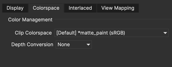
You can also convert the image Depth to float or 8-bit if so required:

These options default to the Mocha OCIO config file, but may show varied options if you are using a custom configuration file.
Defining the Overall Project Color Space
You can define general color settings for the overall Project in the Project Settings dialog.
This gives you all the colour settings in one place to setup the color workflow for clips, display and working space.
To access Project Settings, go to File > Project Settings…
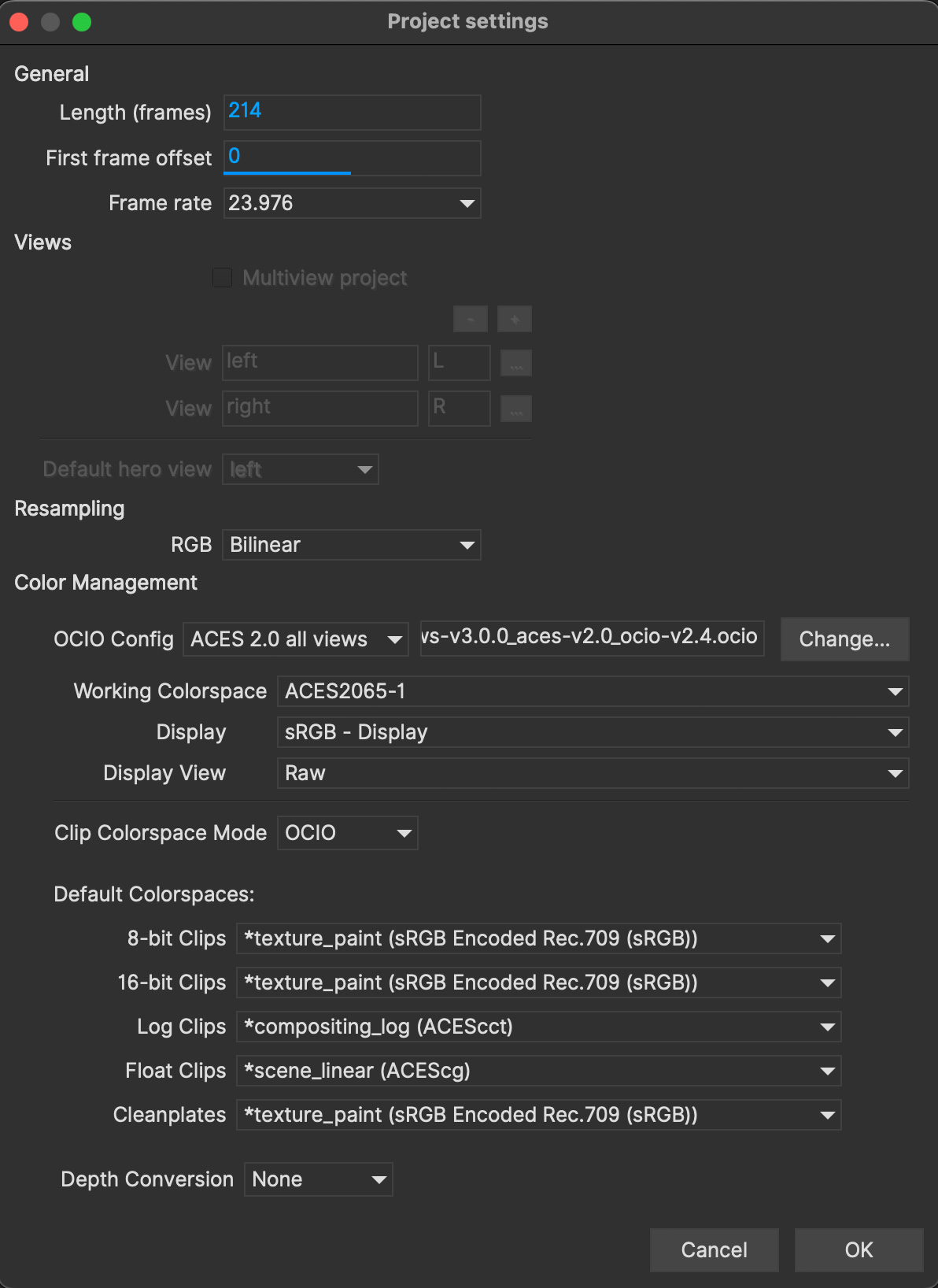
Here the Color Space section is divided into several sections:
OCIO config: Here you can change the OCIO config or reset back to the default.
Working Color Space: The color space or Role you want to work with
Display View: The color view you want to display, such as sRGB, Rec709 etc
Clip Color space Mode: This is either OCIO or Legacy, which is important if you are opening projects from an earlier version of Mocha.
Default Color Spaces: Here you can define what color space to set for clips at various bit depths.
Depth conversion: This lets you define if you want to convert clips by default to 8-bit or Float.
Loading OpenColorIO configurations into Mocha
Loading via the Mocha interface
You can load the path to a different config by accessing any of the config path options in Mocha.
You can load a new config file path via:
The Color tab in Preferences (where you can set defaults)
The Viewer Preference dialog in the view controls
The Project settings of a specific project

Configuration files are usually named as config.ocio in the directory of the color standard you are working with.
Changing the color configuration will automatically update the Working Space, clip space and Display View options.
OCIO Environment Variable
You can define an OCIO environment variable on your system to point to a custom configuration.
For example, if you wanted to use the default Nuke OCIO config, you could define:export OCIO=$HOME/OCIO/nuke-default/config.ocio
Then run Mocha (or your plugin host) from the terminal after defining this variable.
You could also set the OCIO environment variable system-wide using an appropriate OS-specific method (e.g. the Environment Variables dialog in Windows).
If there is no config set, you should see the Mocha default configuration in the interface.
If you set a valid config path, you should see the complete list of supported color spaces.
Once set, the OCIO config will be saved with the project.
Mocha Pro OCIO inside Plugin versions
When using the Mocha Pro plugin, Mocha will try to inherit the current working color space that the host is using.
This is currently supported in the following hosts when OCIO colour management is used:
Boris FX Silhouette
Adobe After Effects
Autodesk Flame 2026.1
If you are not seeing the correct results in your host, you may need to set up the color space manually or use an environment variable (see above).
Setting Defaults for Color Space Workflow
If you’re planning on being in a particular working space for ongoing projects, you can define defaults in Mocha Preferences under the Color tab:
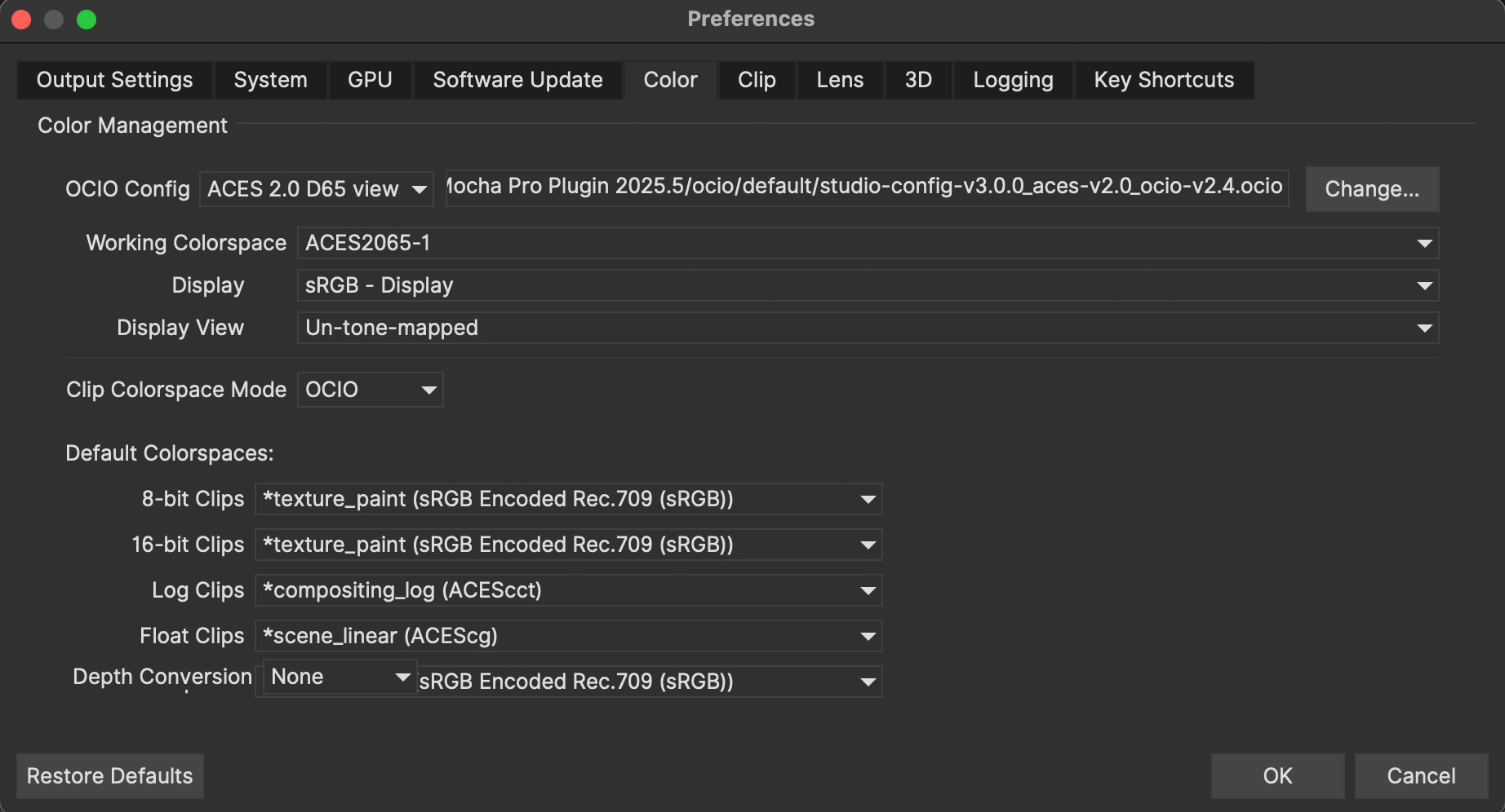
These map exactly like the controls in Project Settings, but will be assigned automatically when creating new projects.
File Formats
| Format support is mainly relevant to the standalone version of Mocha Pro. The Mocha plugin reads the native host source, with the exception of imports done inside the Mocha GUI. |
Reading files via the Mocha Plug-In
If you are using the Mocha plug-in, footage handling is done via the host you are using the plug-in with.
File input happens automatically when you launch the Mocha GUI. Mocha reads the source footage directly from the layer, node or track you have applied Mocha to.
The formats below are only relevant to you if you need to import an external file from disk, such as an additional Insert clip or matte clip.
Reading files via Mocha Standalone
Mocha can read in sequences, still images and video clip files.
In order to read in video clip files, you need to set the way video files are read in via Preferences.
Mocha Standalone has two standards for reading in Media files from disk, which you can set via the Clip section in Preferences:
QuickTime: This is the legacy way of reading clip files. This method will only read clip files that QuickTime supports. In order to use clips with QuickTime (i.e. not image sequences) you must have QuickTime installed. Level of QuickTime support can vary depending on the operating system.
GStreamer: This is an open source multimedia framework for reading many different file formats. It is the current default for reading clips into Mocha.
Supported in this version
Mocha supports most standard movie clip and image sequence formats.
Note that some of the file formats and codecs below will vary depending on whether you have QuickTime or GStreamer selected in Preferences (see above).
Movie clip formats
AVI files (.avi)
DV Stream files (.dv)
MP4 files (.mp4)
MPG files (.mpg)
QuickTime Movie files (.mov and .qt)
RED files (.r3d)
AVCHD files (.mts, .m2t, .m2ts)
Windows Media files (.wmv)
MKV files (.mkv)
MPEG movie files (.mpg, .m2v, .MPG)
MXF files (.mxf)
| Some clip formats such as MXF will use codecs that Mocha does not support. In this case you may need to convert the clip to another format. See 'What to Do if Mocha Does Not Support Your Footage' below. |
Image formats
OpenEXR files (.exr)
OpenEXR 2.0 files (.exr)
Cineon files (.cin)
DPX files (.dpx)
JPEG files (.jpg and .jpeg)
PNG files (.png)
SGI files (.bw, .iris, .rgb, .rgba and .sgi)
TGA files (.tga)
TIFF files (.tif and .TIFF)
Not Directly Supported in this version
These formats are either not supported directly by Mocha or require additional plugins for QuickTime or your system.
Movie clip formats
Cineform files (without supporting codec)
Image formats
RAW image files (.RAW)
BMP files (.bmp)
What to Do if Mocha Does Not Support Your Footage
In the event that you are working in a format that Mocha doesn’t support, we recommend converting the footage to an image sequence.
If you are just tracking, you can use any compressed format such as a JPG sequence and then use your original footage when you apply the data.
If you are going to be doing rendering, such as using Mocha Pro’s remove or insert modules, then we recommend converting to a DPX or TIFF sequence.
Make sure of the following when converting to an image sequence:
The frame rate, aspect ratio and dimensions are the same as the original footage.
If you are creating proxy footage, make sure the aspect ratio and frame rate are the same.
If you are using a particular bit depth, make sure you convert to the same depth if you are using the footage for rendering inside Mocha
If using compressed footage, don’t set the compression too low, as this will create artefacts that may hinder tracking and roto.
Make sure Mocha supports the sequence you are converting to!
If you would prefer to convert to a movie clip format then we recommend a standard format that QuickTime would understand, such as Animation or ProRes.
Command Line
Below you will find a list of command line arguments that can be used to load mocha with preset parameters.
Note that loading a project file on the command line will ignore all other parameters.
Standard usage:
+mocha [arguments] [file…] +
--in frame | Specifies an in-point frame for your footage. The frame value is zero-indexed, so all in points assume a base of 0. For example, If your frames start at 250 and you want to begin at 261, you would type mocha --in 12 myFootage.mov. A 0.5 value will let you set on the second field in interlaced footage, for example: mocha --in 12.5 |
--out frame | Specifies an out-point frame for your footage. The frame value is zero-indexed, so all out points assume a base of 0. For example, If your frames start at 250 and you want to end at 261, you would type mocha --out 12 myFootage.mov. A 0.5 value will let you set on the second field in interlaced footage, for example: mocha --in 12.5 |
--frame-rate fps | Set the frame rate for the imported footage. For example mocha --frame-rate 24 myFootage.mov |
--par par | Set the Pixel Aspect Ratio for the imported footage. For example mocha --par 0.5 myFootage.mov |
--interlace-mode mode | Set the interlacing mode for field ordering and pulldown for the imported footage. For example mocha --interlace-mode 1 myFootage.mov See Table 18.2 below for interlace mode codes. |
0 | Progressive |
1 | Sets interlaced mode UPPER FIELD FIRST |
2 | Sets interlaced mode LOWER FIELD FIRST |
3 | Sets interlaced mode 3:2 PULLDOWN UPPER FIELD FIRST AA |
4 | Sets interlaced mode 3:2 PULLDOWN UPPER FIELD FIRST BB |
5 | Sets interlaced mode 3:2 PULLDOWN UPPER FIELD FIRST BC |
6 | Sets interlaced mode 3:2 PULLDOWN UPPER FIELD FIRST CD |
7 | Sets interlaced mode 3:2 PULLDOWN UPPER FIELD FIRST DD |
8 | Sets interlaced mode 3:2 PULLDOWN LOWER FIELD FIRST AA |
9 | Sets interlaced mode 3:2 PULLDOWN LOWER FIELD FIRST BB |
10 | Sets interlaced mode 3:2 PULLDOWN LOWER FIELD FIRST BC |
11 | Sets interlaced mode 3:2 PULLDOWN LOWER FIELD FIRST CD |
12 | Sets interlaced mode 3:2 PULLDOWN LOWER FIELD FIRST DD |
Environment Variables
Mocha can be initialised with several different environment variables to make it easier to configure across studios.
Checking and Setting Environment Variables
Depending on your system, there are different ways to setup the environment variables. Here is a general guide.
Linux and macOS
The most common way to set environment variables in Linux and macOS is via the command line.
It is best to check if an environment variable is set before you try creating it.
You can do this on Linux or macOS by typing the following into the terminal:
printenv
Alternatively if you want to check the specific variable you can type it after the command:
printenv MOCHA_INIT_SCRIPT
To set an environment variable on Linux or macOS for any programs run from the current shell, you use the export command:
export MOCHA_INIT_SCRIPT="/path/to/my/scripts"
To set an environment variable persistently, including for programs launched from the UI, varies by platform.
Some recommended ways can be:
On macOS set the variable in the
~/.zshrcfile or~/.bash_profiledepending on your version of macOS.On Linux, set it in your
bashrcfile or follow directions for your Linux distribution.
Windows
The most common way to set environment variables in Windows is via the Environment Variables dialog in System Properties.
There are numerous ways to get to this dialog, but the easiest on Windows 10 is to:
Press the Windows key or click the start menu
Type "environment"
Select the "Edit the system environment variables" option that appears at the top of the list.
Click the "Environment Variables…" button at the bottom of the dialog that appears
Once in the dialog, it is best to check if an environment variable is set before you try creating it.
To set an environment variable on Windows:
Click the "New…" button in the user variables section
Enter your environment variable name into the "Variable name" field (such as MOCHA_INIT_SCRIPT)
Enter the value you want to set to this variable in the "Variable Value" field (eg. /path/to/my/scripts)
Click "OK"
Path variables
MOCHA_INIT_SCRIPT
This is used to set the Python init.py script directory.
If the MOCHA_INIT_SCRIPT environment variable points to a file, that file will be used, if it points to a directory, it will look specifically for init.py in that directory.
If unset, the default locations be used.
An example of setting the MOCHA_INIT_SCRIPT variable as a directory:
MOCHA_INIT_SCRIPT='/Users/Mocha/my_scripts/'
See the Mocha Python Guide for more details on how to use init.py and Python scripts in Mocha.
MOCHA_CACHE_PATH
This is used to set the output for the MoTemp cache, where all temporary output is stored.
If the environment variable is set and not empty, a user will not be able to edit the preference in preferences. It will be read-only and set to the MOCHA_CACHE_PATH string.
An example of setting the MOCHA_CACHE_PATH variable as a directory:
MOCHA_CACHE_PATH='/Users/Mocha/my_cache/'
MOCHA_OUTPUT_PATH
This is used to set the output for the Results directory, where projects, mattes and other render output from Mocha Pro Standalone is stored.
If the environment variable is set and not empty, a user will not be able to edit the preference in preferences. It will be read-only and set to the MOCHA_OUTPUT_PATH string.
An example of setting the MOCHA_OUTPUT_PATH variable as a directory:
MOCHA_OUTPUT_PATH='/Users/Mocha/mocha_output/'
OCIO
If you need to point to your OCIO config across many applications, or just want to automate the configuration, you can use the standard OCIO path environment variable.
This should specifically point to the config file rather than the directory, for example:
OCIO='/Users/Mocha/my_LUTS/ocio.config'
Display Variables
QT_SCREEN_SCALE_FACTORS
While not specific to Mocha, this environment variable is mostly used to adjust the scaling of the graphics and text in the GUI when working on high resolution monitors.
If you are having difficulty getting GUI scaling to work, try this variable.
The default for this variable is 1.0, that is, the same scale as the current display scale.
A scale of 0.5 would be half the current display scale, and a scale of 2.0 would be double the size.
An example of setting the QT_SCREEN_SCALE_FACTORS variable to 2.0:
QT_SCREEN_SCALE_FACTORS=2.0
If there is more than one screen, you can separate the displays with semicolons. For example in a two-monitor setup with different resolutions:
QT_SCREEN_SCALE_FACTORS=2;1
MOCHA_QT_SCREEN_SCALE_FACTORS
If you are already using QT_SCREEN_SCALE_FACTORS to affect other programs, you may get conflicting scales with Mocha.
To get around this, you can use MOCHA_QT_SCREEN_SCALE_FACTORS which overrides the more general environment variable above.
An example of setting the MOCHA_QT_SCREEN_SCALE_FACTORS variable to 2.0:
MOCHA_QT_SCREEN_SCALE_FACTORS=2.0
If there is more than one screen, you can separate the displays with semicolons. For example in a two-monitor setup with different resolutions:
MOCHA_QT_SCREEN_SCALE_FACTORS=2;1
License Variables
If you want to point to a default Mocha license directory or file via environment variable, use genarts_LICENSE, which affects all Boris FX products.
It uses the usual RLM syntax, e.g:
`genarts_LICENSE=5053@server-name`
`genarts_LICENSE=/path/to/file.lic`
You can also set up the RLM environment variable to read all .lic files in a directory:
genarts_LICENSE='your/rlm/directory`
If you wish to point all RLM-based software, including products from other companies such as the Foundry, to a common license server, you can point to RLM_LICENSE instead:
RLM_LICENSE='your/rlm/directory`
Installing Node-Locked Licenses
Node-locked Installation
Make sure you have downloaded the correct version of Mocha for your operating system. The licensing system for this version is different from v5 and earlier.
Make sure that your version of Mocha is the product you have purchased (You will not be able to use a Mocha Pro AVX Plugin activation code for Mocha Pro standalone unless you have a multi-host license for example.).
You will need to install the Mocha package:
Apple OS: Double-click the dmg package and drag the application to your application folder
Windows: Double-click the exe package and follow the instructions
Linux: Double-click the installation rpm file and follow the on screen instructions. (64-bit versions of the software will not run on a 32-bit version of Linux).
Standard Node-Locked License Activation for Mocha Pro Standalone
When you purchase your license, you will be emailed a serial number. To activate:
Make sure you are connected to the internet
Open Mocha and choose 'Activate' from the welcome screen or 'Activate nodelocked License' from the help menu.
The BorisFX License Tool will load. Choose "Activate your license now":
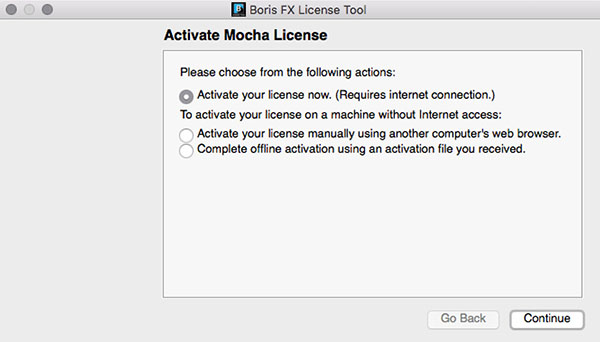
Paste the serial number into the available activation field and click 'Continue'
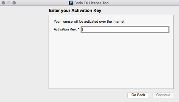
If the activation is successful, details will appear on the next page:

Your license should now be installed and Mocha will close to reset into a licensed state:

Reopen Mocha to start using your licensed version!
If your machine is not connected to the internet, or you are behind a firewall:
Open Mocha and choose 'Activate' from the welcome screen or 'Activate nodelocked license' from the help menu.
. The BorisFX License Tool will load. Choose "Activate your license manually" from the alternative options:
You will be provided with file fields to load a key file:

Download and save the key file that you received from your license email from a computer that has Internet connection.
Transfer the key file to your offline machine you are going to activate via a flash/thumb drive or a shared network.
Select the location of the key file in the first field.
Pick a location for the request file (which will be created) in the second field.
Copy the request file (.req) to a machine with an Internet connection.
Upload it to https://activation.borisfx.com/offline-activation.php.
Save the activation file it returns (via download or email), and copy that back to the offline machine.
Enter its location into to the license tool:
Your license should install automatically and Mocha will close.
Reopen Mocha to start using your licensed version!
Standard Node-Locked License Activation for Mocha Pro Plugin
First locate the licensing button for your host plugin.
Adobe After Effects Plugin License
For After Effects this is called "License…" and sits on the bar of the effect title in your Effect Controls:

Adobe Premiere Plugin License
For Premiere, click the small icon next to the effect title:

Avid Media Composer License
For Avid, click the 'License Control' checkbox under the 'License and Registration' section at the bottom of the plugin controls:

OFX Hosts License
For OFX hosts such as Nuke, Fusion, Hitfilm, Vegas, Flame and so on, click the 'License Control' button under the 'License and Registration' section at the bottom of the plugin controls:

Note that the look of this button will vary in the OFX plugin from host to host, but the location and button name will always be the same.
Follow the regular activation procedure
After that, the rest of the activation procedure is the same as the process above for Mocha standalone. See "Standard Node-Locked License Activation for Mocha Pro Standalone" for more details.
We recommend restarting the host if you see any issues with licensing.
Node-Locked License Troubleshooting
It is important that your Mocha software matches your activation code, so check your purchase order to make sure everything matches up version wise. It may be that you don’t have the correct version of Mocha installed from our download section. This is especially important for legacy software before V5, where a different licensing method is used.
If you are attempting to install via a terminal instead of directly on the machine itself and you are having trouble getting Mocha to install, try installing directly on the machine.
Check to make sure you are not restricted to using certain ports due to a firewall or other admin permissions. When in doubt, temporarily turn your firewalls off for the duration of the installation and then turn them back on when you are done.
Troubleshoot your machine; try uninstalling all your Mocha software, restarting your machine, and installing the software again from scratch, and make sure you follow installation directions off our website exactly. It sounds redundant, but sometimes it’s a great way to figure out what is going on inside your machine.
If all else fails, our support team is happy to help you figure this out. Please contact support!
Installing Floating Licenses
This guide will walk you through the process of installing floating licenses. Installing node-locked licenses does not require the use of the license manager. See above.
Floating licenses - How it works
A floating license allows central administration of your license deployment, avoiding the need to manually activate and deactivate our software on every machine, which is particularly beneficial for large facilities.
Configuring a new machine to use your floating license server is very straightforward and requires no internet connection.
Similarly, replacing a failed machine can be done without needing to contact technical support for the license to be released.
How do I Install the Floating License Server?
Mocha uses the Boris FX RLM License server for floating licenses.
You can download the license server from the Boris FX website. See the steps below.
Floating licenses are easy to set up if if you are familiar with configuring network services, but if you need any help with the process, please contact technical support.
| To configure a license server you must have Administrator (or root) privileges |
Installing Floating Licenses with Online Activation
Download the RLM License Manager from the download section here: RLM License Server.
Run the License Manager file then follow the installation prompts
Open a Web browser and go to: http://SERVERNAME:5054/goforms/activate (Replace “SERVERNAME” with the name of the license server)
Click "BEGIN License Activation"
Enter
activation.genarts.comin the “ISV activation website” field provided and click “Next”.Enter
genartsin the “ISV” fieldCopy and paste your Mocha Activation Key license that you received from your license email into the “License activation key” field. Then, click “Next”
Your Ethernet address will auto-populate in the “License Server or Node-lock hostid” field. Accept the auto-populated Ethernet address
Enter the number of licenses that should be locked to this server in the “License count (for floating licenses)” field. Or just enter 0 to assign all licenses to the specified server. Click “Next”
A default license location will auto-populate in the “License File to create or edit” field. Accept the default license location and click “Next”.
On the “Activation Request Data” screen, verify all the information you have entered, and click “REQUEST LICENSE”
On the “License Activation” page, click on “(Re)start License Server”
Then, on the “Reread/Restart Servers” page, click on “Reread/Restart”
The license server should now be set up.
To confirm that the Boris FX license server is working, go to http://SERVERNAME:5054 (replace SERVERNAME with the name of the server), and click “Status” on the top left hand corner.
genarts should show up under the ISV Servers and it will say Running: Yes.
Installing Floating Licenses with Offline Activation
In cases where you cannot install the license via an Activation code (normally where the server is not connected to the internet) you can manually install your license:
On a machine with internet access, download the RLM License Manager from the download section here: RLM License Server
Install the License Manager on both the machine that has an internet connection AND the offline server you intend to run on (You will use the online machine to get the license for your offline server)
One the online computer, open a web browser and go to: http://SERVERNAME:5054/goforms/activate (Replace “SERVERNAME” with the name of the license server)
Click "BEGIN License Activation"
Enter
activation.genarts.comin the “ISV activation website” field provided and click “Next”.Enter
genartsin the “ISV” fieldCopy and paste your Mocha Activation Key license that you received from your license email into the “License activation key” field. Then, click “Next”
The Ethernet address of the machine you are on will auto-populate in the “License Server or Node-lock hostid” field.
You will need to overwrite it with the Ethernet address of the offline license server.
To find the Ethernet address on the offline license server:For RLM Server v13 and newer:
On Windows: Go to start → Boris FX RLM Server → Get RLM HostID
On Mac: In a console type: “/Library/Application Support/BorisFX/rlm/Get Hostid.py”
On Linux: In a terminal type: /usr/borisfx/rlm/hostid_wrapper.py
For older versions of RLM Server:
On Windows: Go to start → GenArtsRLMServer → Get RLM HostID
On Mac: In a console type: “/Library/Application Support/GenArts/rlm/Get Hostid.py”
On Linux: In a terminal type: /usr/genarts/rlm/hostid_wrapper.py
The command above will print out the results – Get the first mac address from the first line: “Hostid of this machine:“
Enter the mac address into the online “License Server or Node-lock hostid” field.
Enter the number of licenses that should be locked to this server in the “License count (for floating licenses)” field. Or just enter 0 to assign all licenses to the specified server. Click “Next”
A default license location will auto-populate in the “License File to create or edit” field. Replace the default location to a location that you can easily write to and access the file, such as your Desktop or the Downloads folder.
Click "Next"
On the “Activation Request Data” screen, verify all the information you have entered, and click “REQUEST LICENSE”
On the “License Activation” page, click on “(Re)start License Server”
Then, on the “Reread/Restart Servers” page, click on “Reread/Restart”
Transfer the License File on to the offline license server and save the License File to the RLM directory.
For RLM Server v13 and newer:
For Windows:
C:\Program Files\BorisFX\rlmFor Mac:
/Library/Application Support/BorisFX/rlm/For Linux:
/usr/borisfx/rlm/
For older versions of RLM Server:
For Windows:
C:\Program Files (x86)\GenArts\rlmFor Mac:
/Library/Application Support/GenArts/rlm/For Linux:
/usr/genarts/rlm/
Open the License File in a text editor and edit the file with your offline server’s Hostname
Open a Web browser on the offline server, go to http://localhost:5054 and click on “(Re)Start License Server”
This completes the License server set up.
To confirm that the Boris FX license server is working, go to http://SERVERNAME:5054 (replace SERVERNAME with the name of the server), and click “Status” on the top left hand corner. genarts should show up under the ISV Servers and it will say Running: Yes.
Now that everything is installed and activated, you no longer need the RLM server installed on the temporary online computer – you can remove it at this time.
Installing the Floating Client License on a Client Machine (Manual Install)
If you haven’t yet installed the server license, follow the instructions above in How do I Install the Floating License Server.
Once you have the server license installed, perform the following steps to get the client license running:
Install Mocha on the client machine
Get the host line from the server license, which looks like this:
HOST ServerName EthernetAddress PortNumberFor example,
HOST camelot 00000000042e 5053Create a new file in a text editor called
mocha_client.lic. The file name is not important, as long as the '.lic' extension exists.Paste in the HOST line into the client license file and press enter to create a new line
You can either keep the server Mac address in the client or replace it with the word "any". See example below:
mocha_client.licHOST camelot any 5053
Save the file to the Mocha RLM directory. For your particular system this is:
For Windows:
C:\ProgramData\GenArts\rlmFor Mac:
/Library/Application Support/GenArts/rlm/For Linux:
/usr/genarts/rlm/
If the installation is successful, you will now be able to use Mocha
How do I point to the server license using an Environment Variable?
If you want to point to a license file via environment variable, use genarts_LICENSE. It uses the usual RLM syntax, e.g:
genarts_LICENSE=5053@server-name
genarts_LICENSE=/path/to/file.lic
You can also set up the RLM environment variable to read all .lic files in a directory:
genarts_LICENSE=your/rlm/directory
The genarts in the environment variable name must be lower case. |
Troubleshooting Floating Licenses
As with any software, problems may arise during the installation process. Please take a moment to read our troubleshooting section and check for common errors.
If you continue to have issues installing, please contact support and we will be happy to help you. You may contact our support team here: https://borisfx.com/support/open-a-case/
Verify your server license has been successfully installed
Check that your license actually exists on the Server:
For RLM Server v13 and newer:
For Windows:
C:\Program Files\BorisFX\rlmFor Mac:
/Library/Application Support/BorisFX/rlm/For Linux:
/usr/borisfx/rlm/
For older versions of RLM Server:
For Windows:
C:\Program Files (x86)\GenArts\rlmFor Mac:
/Library/Application Support/GenArts/rlm/For Linux:
/usr/genarts/rlm/
Verify your client license has been successfully installed
Check that your client license actually exists on the client machine:
For Windows:
C:\ProgramData\GenArts\rlmFor Mac:
/Library/Application Support/GenArts/rlm/For Linux:
/usr/genarts/rlm/
Verify you are using the latest version of the license server software.
Check to make sure your License Manager is up to date.
Verify there is not a firewall running between the server and the client computer
If your organization needs to run a firewall, you will need to check if the ports for the RLM server are open for use.
Check to make sure your Mocha software matches your activation code
Check your purchase order to make sure everything matches up version wise. It may be that you don’t have the correct version of Mocha installed from our download section. This is especially important for legacy software.
Check for conflicting licenses installed in your licensing folder
If you have more than one Mocha license installed on the server or client machine check to make sure they are not expired licenses. While rare, sometimes these licenses can conflict with any current ones you have on your system.
The client does not connect or see the server host name
If your client machine does not connect to the server based on the server name, try replacing the server name with the IP address of the server instead in the license file. You can easily do this via the License Manager or via a text editor.
When in doubt, check the logs!
Check logs and their paths: Read the logs from Mocha and from your server, they will tell you all about what is happening to your machine.
Check your firewall settings
Check to make sure you are not restricted to using certain ports due to a firewall or other admin permissions. When in doubt, temporarily turn your firewalls off for the duration of the installation and then turn them back on when you are done.
Check your host name settings
If your client machine is not able to connect to the server you may have a networking issue. Try changing the server name in the client license to the IP address of the server instead, or check to see if your host has ".local" appended to the end of it.
You can also do this in any text editor by opening up the client license and server license and manually editing the server name.
Sometimes the best solution is to start again
You might roll your eyes at this one, but try uninstalling, restarting your machine, and installing the software again from scratch. Make sure you follow installation directions off our website exactly. It sounds redundant, but sometimes it’s a great way to troubleshoot what is going on inside your machine.
When all else fails…
Contact us!
Our support team are more than happy to help you fix any floating license issues you may have.
Please contact support here: https://borisfx.com/support/open-a-case/
Installing Render Licenses
This section will discuss the installation of floating render licenses and how they differ from standard interactive floating licensed.
Render Floating Licenses vs Interactive Floating Licenses
A render license is a specific kind of floating license that only allows rendering of Mocha project output, be it inside a plugin or in the standalone application.
When you are using a floating license, it is broken into two parts: The interactive portion and the rendering portion.
For plugins, this is separated like so:
If you open the Mocha GUI in the Mocha Pro Plugin (and a license is available) you are entering the interactive portion.
If you are back in the host and not using interactive elements such as layer choosing or opening the GUI, you are using the rendering portion of the license.
For the standalone, this is separated like so:
If you open the Mocha Pro standalone application (and a license is available) you are entering the interactive portion.
If you have the Mocha Pro standalone application closed and are using the mocharender.py render script, you are utilizing the rendering portion. (See the Python guide for more details on rendering with mocharender.py)
If the interactive license is in use elsewhere or missing, the Mocha GUI will become unlicensed and attempting further work may encrypt your project if you choose to save.
If you have no interactive floating licenses available to render with, additional render licenses can be helpful to let you free up interactive licenses elsewhere.
Workflow for Render Licenses: Example 1
To help illustrate the Render License workflow, let’s look at the following situation:
5 floating licenses (interactive)
10 render licenses (render only)
There is only 1 user
The license server is operating with both sets of licenses.
If only one person is using Mocha on the network, there are 4 interactive and 10 render licenses still available to use.
If only that one person was using Mocha on the network, they would have 15 render machines available for use including the one they were working with.
If another person started working and all machines were in use for rendering, their version of Mocha would be unlicensed, as there would be no available seats.
Workflow for Render Licenses: Example 2
To help illustrate the Render License workflow, let’s look at another situation:
5 floating licenses (interactive)
10 render licenses (render only)
There are 5 users
The license server is operating with both sets of licenses.
There are 5 people working in Mocha.
If another user tries to work on a 6th machine, they will open Mocha unlicensed, because all interactive licenses are in use.
They open an existing project with Mocha in it (or render from the command line), they will be able to render, because all render licenses are available.
Now, say one person wants to send off a render to the network:
If 5 people are using Mocha on the network already, there would be 11 render machines available for use including the one the user was presently working with.
If another person stopped working in Mocha, the interactive license would be released, and a new machine would then be free to either use for work (interactive) or render (non-interactive) by another user.
Installing Render Floating Licenses
The installation of a render license is exactly the same as that of a standard interactive floating license. See the 'Installing Floating Licenses' for a complete guide.
File Management for Rendering on a Network
If you are planning to render either via the Mocha render scripts, an Adobe watch folder or a render farm (for example in Nuke), there are some file workflows you need to adopt.
You will need to make sure the necessary source footage is available for all machines. This includes anything you have imported into the Mocha GUI such as clean plates, insert clips and other imported files.
These files need to be managed by any of the following methods:
Placed in the same file structure on all machines
Relinked manually with an interactive license on all machines
Pointing to the same shared directory.
Failing to set this up may result in incorrect renders.
| If you are using the plugin, you may have imported footage into the Mocha GUI separate from the host source footage. Make sure any imported footage is also available. |
Troubleshooting Mocha issues
Uh Oh. You’ve run into a problem using Mocha. Here are some guides to tackling some roadblocks.
Common Error Messages
Mocha will occasionally throw out an error message when launching, tracking, or performing rendering tasks.
Here are a fe of the more common messages you’ll see, and what they mean.
Tracking
"Tracking Terminated Prematurely"
Often paired with the error "One or more layers were not tracked properly."
This usually means Mocha can’t see where to track next. This can be for a variety of reasons:
Your tracking area is too small or does use enough pixels. Try increasing the size of the spline area or the Min % of pixels used.
The area you are tracking has jumped a significant distance. Try moving back a frame where the tracking was good and increase
the horizontal and/or vertical search area.The area has become completely obscured by something else, the edge of the shot or by motion blur. Check the next frame to see where it went. If
you can’t see an obvious reason, try expanding the spline area, increasing the percentage of pixels used, or move the spline to
a different part of the shot that is coplanar to the area you were tracking.Mocha can’t find the frame. This could be because the host hasn’t sent the plugin a frame or you have a corrupted frame on disk.
Check if you need to purge your cache or free up some memory.
"Tracking failed: couldn’t decompose motion matrix"
This usually means the tracking surface has gone behind the camera and cannot calculate the plane as it’s gone out of bounds.
Normally this happens in tracking with extreme perspetive distortion.
One way around this is to track from the middle of the motion as opposed to starting at one end.
Splines
"Point could not be transformed into frame due to distortion. Error: SEL3"
When you move a point and get this error, there can be a couple of reasons for the problem:
Usually this is a symptom of a bad track. The track has becme very distorted and moving the point is trying to translate within that space.
A corrupted spline. This can happen when points are very close together or have very extreme handles, or are looping in on themselve.
In both situations it’s often best to either find the problem point or keyframe and delete it or remove the spline and attempt to retrack it.
File and clip problems
Frame Not Rendered in Clip
If you open Mocha and you may see a yellow warning that says "Frame X not Rendered in Clip" and the name of a rendered clip, like Remove, Insert, Stabilize etc.
This is very normal. Your render cache is just cleared and needs to be re-rendered.
To go back to seeing your footage, you can either use the top left hand dropdown in the viewer to select "Selected Layer" to view the source clip
or you can click "Render" to re-render the frames of the clip that you are missing.
If you’re wondering why you get this message at all, read on:
When you are in the standalone version of Mocha, you will often see the rendered clip when you reopen, because it is not cleared unless you tell it to.
In the plugin, however, the render is always cleared on exit. You won’t ever see the render when you go back to the Mocha GUI in the plugin, because it is always removed.
Because a plugin environment relies on the host’s images, if any changes are made to the source footage (brightness, color correction, editing, effects etc) the plugin needs to be updated with the new information.
If we retain the old cached render, the output wouldn’t reflect the changes made by the user in the host and you would get inconsistent results.
So, when you see a message saying “Frame X not rendered”, it literally just means there isn’t currently a frame to view, because it’s either never been rendered, or it’s been cleared.
"Failed to open file"
This error will also say "The file is corrupted or in an unsupported format."
Generally the reason this occurs is for that very reason: The file can’t be read because it’s not currently supported.
In most cases the best way to get back to work is to convert the clip in question to an image sequence such as TIF or DPX.
You can also try to convert to one of the suppported media formats listed in the File Formats section of the user guide.
"Bad Argument Provided"
If you get this error, it usually means the host hasn’t sent Mocha any readable information.
This can be for several reasons:
The host has run out of cache memory and can’t supply any new frames
The node or layer you’ve added the Mocha effect to has hold or retiming applied to it and is feeding Mocha incorrect frames.
A frame is missing or corrupted
In most cases, you need to solve this on the host end and find where the problem has occured. If you’re unsure, please contact Boris FX support.
“Clip must be converted to 8 bit grayscale for use as a matte clip.”
If you need to use a matte clip in your project you need to import a Gray formatted file, not RGB.
If you don’t have a file that supports Gray as a color format, we do the conversion for you and save the resulting clip to the clip cache.
License problems
"Licensing error: heartbeat failure"
The error occurs when a floating license client loses connection to the license the server.
Normally to fix this you need to restablish the connection to the license server.
Common problems encountered when working with Mocha
Tracking
Tracking slips or becomes erratic
In most cases, a slipping, drifting or jumping track is going to be because Mocha
cannot find the area you were tracking on the next frame.
There can be multiple causes for this, so let’s take a look at some common cases.
The tracking area has been interrupted or obscured
This is probably the most common. When the area you are tracking has something else enter the layer shape, it can throw off the track.
This can be a small, high-contrast object entering the edges of the shape or even completely covering the main area.
It can also be caused by the area itself updating, such as screens or reflective objects.
It’s important to check over your clip to see if anything (e.g. a bird, elbow, hair, etc) has drifted into the space you are tracking. If it has, you need to either adjust your
tracking shape to avoid the object, or create a separate layer mask on top of your tracking layer.
In cases where the foreground interruption is very large, you may not have enough information left in the tracking shape to get any worthwhile tracking data.
In this case, you may need to track a coplanar area or manually adjust the tracking to ignore the problem.
The tracking area is moving very fast
If an object is moving fast, you can get two problems: The tracking not being able to keep up and the introduction of motion blur.
If the object is moving very fast vertically or horizontally, you may need to turn off the "Auto" checkboxes in the search area parameters and enter a larger value.
If the object is rotating or zooming/scaling very quickly, you can also adjust the angle and zoom parameters to provide an estimate of the speed of motion.
For motion blur, it can be trickier. Start by increasing the Min % of Pixels used to see if there is
enough detail to keep Mocha latched on. If the track is still slipping, it may be worth continuing the track and adjusting the drift with
AjustTrack afterwards.
Third Party Open Source and Commercial Licenses Used by Mocha
Mocha uses the following third-party libraries and commercial licenses.
Where relevant, full license text is listed under each heading.
Qt 6.5.4
Qt is available under the GNU Lesser General Public License version 3.
The source code for Qt 6.5.4 can be obtained from https://github.com/boris-fx/qt5/tree/bfx/6.5.4
            GNU LESSER GENERAL PUBLIC LICENSE

 The Qt Toolkit is Copyright (C) 2015 The Qt Company Ltd.
 Contact: http://www.qt.io/licensing/

 You may use, distribute and copy the Qt Toolkit under the terms of
 GNU Lesser General Public License version 3, which is displayed below.
 This license makes reference to the version 3 of the GNU General
 Public License, which you can find in the LICENSE.GPLv3 file.

-------------------------------------------------------------------------

            GNU LESSER GENERAL PUBLIC LICENSE
                Version 3, 29 June 2007

 Copyright © 2007 Free Software Foundation, Inc. <http://fsf.org/>
Everyone is permitted to copy and distribute verbatim copies of this
licensedocument, but changing it is not allowed.

This version of the GNU Lesser General Public License incorporates
the terms and conditions of version 3 of the GNU General Public
License, supplemented by the additional permissions listed below.

0. Additional Definitions.

 As used herein, “this License” refers to version 3 of the GNU Lesser
General Public License, and the “GNU GPL” refers to version 3 of the
GNU General Public License.

 “The Library” refers to a covered work governed by this License,
other than an Application or a Combined Work as defined below.

 An “Application” is any work that makes use of an interface provided
by the Library, but which is not otherwise based on the Library.
Defining a subclass of a class defined by the Library is deemed a mode
of using an interface provided by the Library.

 A “Combined Work” is a work produced by combining or linking an
Application with the Library. The particular version of the Library
with which the Combined Work was made is also called the “Linked
Version”.

 The “Minimal Corresponding Source” for a Combined Work means the
Corresponding Source for the Combined Work, excluding any source code
for portions of the Combined Work that, considered in isolation, are
based on the Application, and not on the Linked Version.

 The “Corresponding Application Code” for a Combined Work means the
object code and/or source code for the Application, including any data
and utility programs needed for reproducing the Combined Work from the
Application, but excluding the System Libraries of the Combined Work.

1. Exception to Section 3 of the GNU GPL.

 You may convey a covered work under sections 3 and 4 of this License
without being bound by section 3 of the GNU GPL.

2. Conveying Modified Versions.

 If you modify a copy of the Library, and, in your modifications, a
facility refers to a function or data to be supplied by an Application
that uses the facility (other than as an argument passed when the
facility is invoked), then you may convey a copy of the modified
version:

    a) under this License, provided that you make a good faith effort
    to ensure that, in the event an Application does not supply the
    function or data, the facility still operates, and performs
    whatever part of its purpose remains meaningful, or

    b) under the GNU GPL, with none of the additional permissions of
    this License applicable to that copy.

3. Object Code Incorporating Material from Library Header Files.

 The object code form of an Application may incorporate material from
a header file that is part of the Library. You may convey such object
code under terms of your choice, provided that, if the incorporated
material is not limited to numerical parameters, data structure
layouts and accessors, or small macros, inline functions and templates
(ten or fewer lines in length), you do both of the following:

    a) Give prominent notice with each copy of the object code that
    the Library is used in it and that the Library and its use are
    covered by this License.

    b) Accompany the object code with a copy of the GNU GPL and this
    license document.

4. Combined Works.

 You may convey a Combined Work under terms of your choice that, taken
together, effectively do not restrict modification of the portions of
the Library contained in the Combined Work and reverse engineering for
debugging such modifications, if you also do each of the following:

    a) Give prominent notice with each copy of the Combined Work that
    the Library is used in it and that the Library and its use are
    covered by this License.

    b) Accompany the Combined Work with a copy of the GNU GPL and this
    license document.

    c) For a Combined Work that displays copyright notices during
    execution, include the copyright notice for the Library among
    these notices, as well as a reference directing the user to the
    copies of the GNU GPL and this license document.

    d) Do one of the following:

        0) Convey the Minimal Corresponding Source under the terms of
        this License, and the Corresponding Application Code in a form
        suitable for, and under terms that permit, the user to
        recombine or relink the Application with a modified version of
        the Linked Version to produce a modified Combined Work, in the
        manner specified by section 6 of the GNU GPL for conveying
        Corresponding Source.

        1) Use a suitable shared library mechanism for linking with
        the Library. A suitable mechanism is one that (a) uses at run
        time a copy of the Library already present on the user's
        computer system, and (b) will operate properly with a modified
        version of the Library that is interface-compatible with the
        Linked Version.

    e) Provide Installation Information, but only if you would
    otherwise be required to provide such information under section 6
    of the GNU GPL, and only to the extent that such information is
    necessary to install and execute a modified version of the
    Combined Work produced by recombining or relinking the Application
    with a modified version of the Linked Version. (If you use option
    4d0, the Installation Information must accompany the Minimal
    Corresponding Source and Corresponding Application Code. If you
    use option 4d1, you must provide the Installation Information in
    the manner specified by section 6 of the GNU GPL for conveying
    Corresponding Source.)

5. Combined Libraries.

 You may place library facilities that are a work based on the Library
side by side in a single library together with other library
facilities that are not Applications and are not covered by this
License, and convey such a combined library under terms of your
choice, if you do both of the following:

    a) Accompany the combined library with a copy of the same work
    based on the Library, uncombined with any other library
    facilities, conveyed under the terms of this License.

    b) Give prominent notice with the combined library that part of
    it is a work based on the Library, and explaining where to find
    the accompanying uncombined form of the same work.

6. Revised Versions of the GNU Lesser General Public License.

 The Free Software Foundation may publish revised and/or new versions
of the GNU Lesser General Public License from time to time. Such new
versions will be similar in spirit to the present version, but may
differ in detail to address new problems or concerns.

Each version is given a distinguishing version number. If the Library
as you received it specifies that a certain numbered version of the
GNU Lesser General Public License “or any later version” applies to
it, you have the option of following the terms and conditions either
of that published version or of any later version published by the
Free Software Foundation. If the Library as you received it does not
specify a version number of the GNU Lesser General Public License,
you may choose any version of the GNU Lesser General Public License
ever published by the Free Software Foundation.

If the Library as you received it specifies that a proxy can decide
whether future versions of the GNU Lesser General Public License shall
apply, that proxy's public statement of acceptance of any version is
permanent authorization for you to choose that version for the Library.
Python
PYTHON SOFTWARE FOUNDATION LICENSE VERSION 2

1. This LICENSE AGREEMENT is between the Python Software Foundation
("PSF"), and the Individual or Organization ("Licensee") accessing and
otherwise using this software ("Python") in source or binary form and
its associated documentation.

2. Subject to the terms and conditions of this License Agreement, PSF hereby
grants Licensee a nonexclusive, royalty-free, world-wide license to reproduce,
analyze, test, perform and/or display publicly, prepare derivative works,
distribute, and otherwise use Python alone or in any derivative version,
provided, however, that PSF's License Agreement and PSF's notice of copyright,
i.e., "Copyright (c) 2001, 2002, 2003, 2004, 2005, 2006, 2007, 2008, 2009, 2010,
2011, 2012, 2013, 2014, 2015, 2016, 2017, 2018, 2019, 2020, 2021, 2022, 2023 Python Software Foundation;
All Rights Reserved" are retained in Python alone or in any derivative version
prepared by Licensee.

3. In the event Licensee prepares a derivative work that is based on
or incorporates Python or any part thereof, and wants to make
the derivative work available to others as provided herein, then
Licensee hereby agrees to include in any such work a brief summary of
the changes made to Python.

4. PSF is making Python available to Licensee on an "AS IS"
basis.  PSF MAKES NO REPRESENTATIONS OR WARRANTIES, EXPRESS OR
IMPLIED.  BY WAY OF EXAMPLE, BUT NOT LIMITATION, PSF MAKES NO AND
DISCLAIMS ANY REPRESENTATION OR WARRANTY OF MERCHANTABILITY OR FITNESS
FOR ANY PARTICULAR PURPOSE OR THAT THE USE OF PYTHON WILL NOT
INFRINGE ANY THIRD PARTY RIGHTS.

5. PSF SHALL NOT BE LIABLE TO LICENSEE OR ANY OTHER USERS OF PYTHON
FOR ANY INCIDENTAL, SPECIAL, OR CONSEQUENTIAL DAMAGES OR LOSS AS
A RESULT OF MODIFYING, DISTRIBUTING, OR OTHERWISE USING PYTHON,
OR ANY DERIVATIVE THEREOF, EVEN IF ADVISED OF THE POSSIBILITY THEREOF.

6. This License Agreement will automatically terminate upon a material
breach of its terms and conditions.

7. Nothing in this License Agreement shall be deemed to create any
relationship of agency, partnership, or joint venture between PSF and
Licensee.  This License Agreement does not grant permission to use PSF
trademarks or trade name in a trademark sense to endorse or promote
products or services of Licensee, or any third party.

8. By copying, installing or otherwise using Python, Licensee
agrees to be bound by the terms and conditions of this License
Agreement.
OpenColorIO
Copyright Contributors to the OpenColorIO Project.

Redistribution and use in source and binary forms, with or without
modification, are permitted provided that the following conditions are
met:

* Redistributions of source code must retain the above copyright
  notice, this list of conditions and the following disclaimer.
* Redistributions in binary form must reproduce the above copyright
  notice, this list of conditions and the following disclaimer in the
  documentation and/or other materials provided with the distribution.
* Neither the name of the copyright holder nor the names of its
  contributors may be used to endorse or promote products derived from
  this software without specific prior written permission.

THIS SOFTWARE IS PROVIDED BY THE COPYRIGHT HOLDERS AND CONTRIBUTORS
"AS IS" AND ANY EXPRESS OR IMPLIED WARRANTIES, INCLUDING, BUT NOT
LIMITED TO, THE IMPLIED WARRANTIES OF MERCHANTABILITY AND FITNESS FOR
A PARTICULAR PURPOSE ARE DISCLAIMED. IN NO EVENT SHALL THE COPYRIGHT
HOLDER OR CONTRIBUTORS BE LIABLE FOR ANY DIRECT, INDIRECT, INCIDENTAL,
SPECIAL, EXEMPLARY, OR CONSEQUENTIAL DAMAGES (INCLUDING, BUT NOT
LIMITED TO, PROCUREMENT OF SUBSTITUTE GOODS OR SERVICES; LOSS OF USE,
DATA, OR PROFITS; OR BUSINESS INTERRUPTION) HOWEVER CAUSED AND ON ANY
THEORY OF LIABILITY, WHETHER IN CONTRACT, STRICT LIABILITY, OR TORT
(INCLUDING NEGLIGENCE OR OTHERWISE) ARISING IN ANY WAY OUT OF THE USE
OF THIS SOFTWARE, EVEN IF ADVISED OF THE POSSIBILITY OF SUCH DAMAGE.
OpenSSL
                                 Apache License
                           Version 2.0, January 2004
                        https://www.apache.org/licenses/

   TERMS AND CONDITIONS FOR USE, REPRODUCTION, AND DISTRIBUTION

   1. Definitions.

      "License" shall mean the terms and conditions for use, reproduction,
      and distribution as defined by Sections 1 through 9 of this document.

      "Licensor" shall mean the copyright owner or entity authorized by
      the copyright owner that is granting the License.

      "Legal Entity" shall mean the union of the acting entity and all
      other entities that control, are controlled by, or are under common
      control with that entity. For the purposes of this definition,
      "control" means (i) the power, direct or indirect, to cause the
      direction or management of such entity, whether by contract or
      otherwise, or (ii) ownership of fifty percent (50%) or more of the
      outstanding shares, or (iii) beneficial ownership of such entity.

      "You" (or "Your") shall mean an individual or Legal Entity
      exercising permissions granted by this License.

      "Source" form shall mean the preferred form for making modifications,
      including but not limited to software source code, documentation
      source, and configuration files.

      "Object" form shall mean any form resulting from mechanical
      transformation or translation of a Source form, including but
      not limited to compiled object code, generated documentation,
      and conversions to other media types.

      "Work" shall mean the work of authorship, whether in Source or
      Object form, made available under the License, as indicated by a
      copyright notice that is included in or attached to the work
      (an example is provided in the Appendix below).

      "Derivative Works" shall mean any work, whether in Source or Object
      form, that is based on (or derived from) the Work and for which the
      editorial revisions, annotations, elaborations, or other modifications
      represent, as a whole, an original work of authorship. For the purposes
      of this License, Derivative Works shall not include works that remain
      separable from, or merely link (or bind by name) to the interfaces of,
      the Work and Derivative Works thereof.

      "Contribution" shall mean any work of authorship, including
      the original version of the Work and any modifications or additions
      to that Work or Derivative Works thereof, that is intentionally
      submitted to Licensor for inclusion in the Work by the copyright owner
      or by an individual or Legal Entity authorized to submit on behalf of
      the copyright owner. For the purposes of this definition, "submitted"
      means any form of electronic, verbal, or written communication sent
      to the Licensor or its representatives, including but not limited to
      communication on electronic mailing lists, source code control systems,
      and issue tracking systems that are managed by, or on behalf of, the
      Licensor for the purpose of discussing and improving the Work, but
      excluding communication that is conspicuously marked or otherwise
      designated in writing by the copyright owner as "Not a Contribution."

      "Contributor" shall mean Licensor and any individual or Legal Entity
      on behalf of whom a Contribution has been received by Licensor and
      subsequently incorporated within the Work.

   2. Grant of Copyright License. Subject to the terms and conditions of
      this License, each Contributor hereby grants to You a perpetual,
      worldwide, non-exclusive, no-charge, royalty-free, irrevocable
      copyright license to reproduce, prepare Derivative Works of,
      publicly display, publicly perform, sublicense, and distribute the
      Work and such Derivative Works in Source or Object form.

   3. Grant of Patent License. Subject to the terms and conditions of
      this License, each Contributor hereby grants to You a perpetual,
      worldwide, non-exclusive, no-charge, royalty-free, irrevocable
      (except as stated in this section) patent license to make, have made,
      use, offer to sell, sell, import, and otherwise transfer the Work,
      where such license applies only to those patent claims licensable
      by such Contributor that are necessarily infringed by their
      Contribution(s) alone or by combination of their Contribution(s)
      with the Work to which such Contribution(s) was submitted. If You
      institute patent litigation against any entity (including a
      cross-claim or counterclaim in a lawsuit) alleging that the Work
      or a Contribution incorporated within the Work constitutes direct
      or contributory patent infringement, then any patent licenses
      granted to You under this License for that Work shall terminate
      as of the date such litigation is filed.

   4. Redistribution. You may reproduce and distribute copies of the
      Work or Derivative Works thereof in any medium, with or without
      modifications, and in Source or Object form, provided that You
      meet the following conditions:

      (a) You must give any other recipients of the Work or
          Derivative Works a copy of this License; and

      (b) You must cause any modified files to carry prominent notices
          stating that You changed the files; and

      (c) You must retain, in the Source form of any Derivative Works
          that You distribute, all copyright, patent, trademark, and
          attribution notices from the Source form of the Work,
          excluding those notices that do not pertain to any part of
          the Derivative Works; and

      (d) If the Work includes a "NOTICE" text file as part of its
          distribution, then any Derivative Works that You distribute must
          include a readable copy of the attribution notices contained
          within such NOTICE file, excluding those notices that do not
          pertain to any part of the Derivative Works, in at least one
          of the following places: within a NOTICE text file distributed
          as part of the Derivative Works; within the Source form or
          documentation, if provided along with the Derivative Works; or,
          within a display generated by the Derivative Works, if and
          wherever such third-party notices normally appear. The contents
          of the NOTICE file are for informational purposes only and
          do not modify the License. You may add Your own attribution
          notices within Derivative Works that You distribute, alongside
          or as an addendum to the NOTICE text from the Work, provided
          that such additional attribution notices cannot be construed
          as modifying the License.

      You may add Your own copyright statement to Your modifications and
      may provide additional or different license terms and conditions
      for use, reproduction, or distribution of Your modifications, or
      for any such Derivative Works as a whole, provided Your use,
      reproduction, and distribution of the Work otherwise complies with
      the conditions stated in this License.

   5. Submission of Contributions. Unless You explicitly state otherwise,
      any Contribution intentionally submitted for inclusion in the Work
      by You to the Licensor shall be under the terms and conditions of
      this License, without any additional terms or conditions.
      Notwithstanding the above, nothing herein shall supersede or modify
      the terms of any separate license agreement you may have executed
      with Licensor regarding such Contributions.

   6. Trademarks. This License does not grant permission to use the trade
      names, trademarks, service marks, or product names of the Licensor,
      except as required for reasonable and customary use in describing the
      origin of the Work and reproducing the content of the NOTICE file.

   7. Disclaimer of Warranty. Unless required by applicable law or
      agreed to in writing, Licensor provides the Work (and each
      Contributor provides its Contributions) on an "AS IS" BASIS,
      WITHOUT WARRANTIES OR CONDITIONS OF ANY KIND, either express or
      implied, including, without limitation, any warranties or conditions
      of TITLE, NON-INFRINGEMENT, MERCHANTABILITY, or FITNESS FOR A
      PARTICULAR PURPOSE. You are solely responsible for determining the
      appropriateness of using or redistributing the Work and assume any
      risks associated with Your exercise of permissions under this License.

   8. Limitation of Liability. In no event and under no legal theory,
      whether in tort (including negligence), contract, or otherwise,
      unless required by applicable law (such as deliberate and grossly
      negligent acts) or agreed to in writing, shall any Contributor be
      liable to You for damages, including any direct, indirect, special,
      incidental, or consequential damages of any character arising as a
      result of this License or out of the use or inability to use the
      Work (including but not limited to damages for loss of goodwill,
      work stoppage, computer failure or malfunction, or any and all
      other commercial damages or losses), even if such Contributor
      has been advised of the possibility of such damages.

   9. Accepting Warranty or Additional Liability. While redistributing
      the Work or Derivative Works thereof, You may choose to offer,
      and charge a fee for, acceptance of support, warranty, indemnity,
      or other liability obligations and/or rights consistent with this
      License. However, in accepting such obligations, You may act only
      on Your own behalf and on Your sole responsibility, not on behalf
      of any other Contributor, and only if You agree to indemnify,
      defend, and hold each Contributor harmless for any liability
      incurred by, or claims asserted against, such Contributor by reason
      of your accepting any such warranty or additional liability.

   END OF TERMS AND CONDITIONS
libpng
PNG Reference Library License version 1 (for libpng 0.5 through 1.6.35)

libpng versions 1.0.7, July 1, 2000, through 1.6.35, July 15, 2018 are
Copyright (c) 2000-2002, 2004, 2006-2018 Glenn Randers-Pehrson, are
derived from libpng-1.0.6, and are distributed according to the same
disclaimer and license as libpng-1.0.6 with the following individuals
added to the list of Contributing Authors:

    Simon-Pierre Cadieux
    Eric S. Raymond
    Mans Rullgard
    Cosmin Truta
    Gilles Vollant
    James Yu
    Mandar Sahastrabuddhe
    Google Inc.
    Vadim Barkov

and with the following additions to the disclaimer:

    There is no warranty against interference with your enjoyment of
    the library or against infringement.  There is no warranty that our
    efforts or the library will fulfill any of your particular purposes
    or needs.  This library is provided with all faults, and the entire
    risk of satisfactory quality, performance, accuracy, and effort is
    with the user.

Some files in the "contrib" directory and some configure-generated
files that are distributed with libpng have other copyright owners, and
are released under other open source licenses.

libpng versions 0.97, January 1998, through 1.0.6, March 20, 2000, are
Copyright (c) 1998-2000 Glenn Randers-Pehrson, are derived from
libpng-0.96, and are distributed according to the same disclaimer and
license as libpng-0.96, with the following individuals added to the
list of Contributing Authors:

    Tom Lane
    Glenn Randers-Pehrson
    Willem van Schaik

libpng versions 0.89, June 1996, through 0.96, May 1997, are
Copyright (c) 1996-1997 Andreas Dilger, are derived from libpng-0.88,
and are distributed according to the same disclaimer and license as
libpng-0.88, with the following individuals added to the list of
Contributing Authors:

    John Bowler
    Kevin Bracey
    Sam Bushell
    Magnus Holmgren
    Greg Roelofs
    Tom Tanner

Some files in the "scripts" directory have other copyright owners,
but are released under this license.

libpng versions 0.5, May 1995, through 0.88, January 1996, are
Copyright (c) 1995-1996 Guy Eric Schalnat, Group 42, Inc.

For the purposes of this copyright and license, "Contributing Authors"
is defined as the following set of individuals:

    Andreas Dilger
    Dave Martindale
    Guy Eric Schalnat
    Paul Schmidt
    Tim Wegner

The PNG Reference Library is supplied "AS IS".  The Contributing
Authors and Group 42, Inc. disclaim all warranties, expressed or
implied, including, without limitation, the warranties of
merchantability and of fitness for any purpose.  The Contributing
Authors and Group 42, Inc. assume no liability for direct, indirect,
incidental, special, exemplary, or consequential damages, which may
result from the use of the PNG Reference Library, even if advised of
the possibility of such damage.

Permission is hereby granted to use, copy, modify, and distribute this
source code, or portions hereof, for any purpose, without fee, subject
to the following restrictions:

 1. The origin of this source code must not be misrepresented.

 2. Altered versions must be plainly marked as such and must not
    be misrepresented as being the original source.

 3. This Copyright notice may not be removed or altered from any
    source or altered source distribution.

The Contributing Authors and Group 42, Inc. specifically permit,
without fee, and encourage the use of this source code as a component
to supporting the PNG file format in commercial products.  If you use
this source code in a product, acknowledgment is not required but would
be appreciated.
libjpeg
LICENSE TERMS (ships as a part of the libjpeg package in the README file)

1. We don't promise that this software works.  (But if you find any bugs,
   please let us know!)
2. You can use this software for whatever you want.  You don't have to pay us.
3. You may not pretend that you wrote this software.  If you use it in a
   program, you must acknowledge somewhere in your documentation that
   you've used the IJG code.

In legalese:

The authors make NO WARRANTY or representation, either express or implied,
with respect to this software, its quality, accuracy, merchantability, or
fitness for a particular purpose.  This software is provided "AS IS", and you,
its user, assume the entire risk as to its quality and accuracy.

This software is copyright (C) 1991-2016, Thomas G. Lane, Guido Vollbeding.
All Rights Reserved except as specified below.

Permission is hereby granted to use, copy, modify, and distribute this
software (or portions thereof) for any purpose, without fee, subject to these
conditions:
(1) If any part of the source code for this software is distributed, then this
README file must be included, with this copyright and no-warranty notice
unaltered; and any additions, deletions, or changes to the original files
must be clearly indicated in accompanying documentation.
(2) If only executable code is distributed, then the accompanying
documentation must state that "this software is based in part on the work of
the Independent JPEG Group".
(3) Permission for use of this software is granted only if the user accepts
full responsibility for any undesirable consequences; the authors accept
NO LIABILITY for damages of any kind.

These conditions apply to any software derived from or based on the IJG code,
not just to the unmodified library.  If you use our work, you ought to
acknowledge us.

Permission is NOT granted for the use of any IJG author's name or company name
in advertising or publicity relating to this software or products derived from
it.  This software may be referred to only as "the Independent JPEG Group's
software".

We specifically permit and encourage the use of this software as the basis of
commercial products, provided that all warranty or liability claims are
assumed by the product vendor.
PySide2
The source code for PySide2 can be obtained from https://github.com/boris-fx/mocha-pyside/tree/bfx/5.15.15
PySide2 uses Lesser General Public License (LGPL) version 3
            GNU LESSER GENERAL PUBLIC LICENSE

 The Qt Toolkit is Copyright (C) 2015 The Qt Company Ltd.
 Contact: http://www.qt.io/licensing/

 You may use, distribute and copy the Qt Toolkit under the terms of
 GNU Lesser General Public License version 3, which is displayed below.
 This license makes reference to the version 3 of the GNU General
 Public License, which you can find in the LICENSE.GPLv3 file.

-------------------------------------------------------------------------

                   GNU LESSER GENERAL PUBLIC LICENSE
                       Version 3, 29 June 2007

 Copyright (C) 2007 Free Software Foundation, Inc. <http://fsf.org/>
 Everyone is permitted to copy and distribute verbatim copies
 of this license document, but changing it is not allowed.


  This version of the GNU Lesser General Public License incorporates
the terms and conditions of version 3 of the GNU General Public
License, supplemented by the additional permissions listed below.

  0. Additional Definitions.

  As used herein, "this License" refers to version 3 of the GNU Lesser
General Public License, and the "GNU GPL" refers to version 3 of the GNU
General Public License.

  "The Library" refers to a covered work governed by this License,
other than an Application or a Combined Work as defined below.

  An "Application" is any work that makes use of an interface provided
by the Library, but which is not otherwise based on the Library.
Defining a subclass of a class defined by the Library is deemed a mode
of using an interface provided by the Library.

  A "Combined Work" is a work produced by combining or linking an
Application with the Library.  The particular version of the Library
with which the Combined Work was made is also called the "Linked
Version".

  The "Minimal Corresponding Source" for a Combined Work means the
Corresponding Source for the Combined Work, excluding any source code
for portions of the Combined Work that, considered in isolation, are
based on the Application, and not on the Linked Version.

  The "Corresponding Application Code" for a Combined Work means the
object code and/or source code for the Application, including any data
and utility programs needed for reproducing the Combined Work from the
Application, but excluding the System Libraries of the Combined Work.

  1. Exception to Section 3 of the GNU GPL.

  You may convey a covered work under sections 3 and 4 of this License
without being bound by section 3 of the GNU GPL.

  2. Conveying Modified Versions.

  If you modify a copy of the Library, and, in your modifications, a
facility refers to a function or data to be supplied by an Application
that uses the facility (other than as an argument passed when the
facility is invoked), then you may convey a copy of the modified
version:

   a) under this License, provided that you make a good faith effort to
   ensure that, in the event an Application does not supply the
   function or data, the facility still operates, and performs
   whatever part of its purpose remains meaningful, or

   b) under the GNU GPL, with none of the additional permissions of
   this License applicable to that copy.

  3. Object Code Incorporating Material from Library Header Files.

  The object code form of an Application may incorporate material from
a header file that is part of the Library.  You may convey such object
code under terms of your choice, provided that, if the incorporated
material is not limited to numerical parameters, data structure
layouts and accessors, or small macros, inline functions and templates
(ten or fewer lines in length), you do both of the following:

   a) Give prominent notice with each copy of the object code that the
   Library is used in it and that the Library and its use are
   covered by this License.

   b) Accompany the object code with a copy of the GNU GPL and this license
   document.

  4. Combined Works.

  You may convey a Combined Work under terms of your choice that,
taken together, effectively do not restrict modification of the
portions of the Library contained in the Combined Work and reverse
engineering for debugging such modifications, if you also do each of
the following:

   a) Give prominent notice with each copy of the Combined Work that
   the Library is used in it and that the Library and its use are
   covered by this License.

   b) Accompany the Combined Work with a copy of the GNU GPL and this license
   document.

   c) For a Combined Work that displays copyright notices during
   execution, include the copyright notice for the Library among
   these notices, as well as a reference directing the user to the
   copies of the GNU GPL and this license document.

   d) Do one of the following:

       0) Convey the Minimal Corresponding Source under the terms of this
       License, and the Corresponding Application Code in a form
       suitable for, and under terms that permit, the user to
       recombine or relink the Application with a modified version of
       the Linked Version to produce a modified Combined Work, in the
       manner specified by section 6 of the GNU GPL for conveying
       Corresponding Source.

       1) Use a suitable shared library mechanism for linking with the
       Library.  A suitable mechanism is one that (a) uses at run time
       a copy of the Library already present on the user's computer
       system, and (b) will operate properly with a modified version
       of the Library that is interface-compatible with the Linked
       Version.

   e) Provide Installation Information, but only if you would otherwise
   be required to provide such information under section 6 of the
   GNU GPL, and only to the extent that such information is
   necessary to install and execute a modified version of the
   Combined Work produced by recombining or relinking the
   Application with a modified version of the Linked Version. (If
   you use option 4d0, the Installation Information must accompany
   the Minimal Corresponding Source and Corresponding Application
   Code. If you use option 4d1, you must provide the Installation
   Information in the manner specified by section 6 of the GNU GPL
   for conveying Corresponding Source.)

  5. Combined Libraries.

  You may place library facilities that are a work based on the
Library side by side in a single library together with other library
facilities that are not Applications and are not covered by this
License, and convey such a combined library under terms of your
choice, if you do both of the following:

   a) Accompany the combined library with a copy of the same work based
   on the Library, uncombined with any other library facilities,
   conveyed under the terms of this License.

   b) Give prominent notice with the combined library that part of it
   is a work based on the Library, and explaining where to find the
   accompanying uncombined form of the same work.

  6. Revised Versions of the GNU Lesser General Public License.

  The Free Software Foundation may publish revised and/or new versions
of the GNU Lesser General Public License from time to time. Such new
versions will be similar in spirit to the present version, but may
differ in detail to address new problems or concerns.

  Each version is given a distinguishing version number. If the
Library as you received it specifies that a certain numbered version
of the GNU Lesser General Public License "or any later version"
applies to it, you have the option of following the terms and
conditions either of that published version or of any later version
published by the Free Software Foundation. If the Library as you
received it does not specify a version number of the GNU Lesser
General Public License, you may choose any version of the GNU Lesser
General Public License ever published by the Free Software Foundation.

  If the Library as you received it specifies that a proxy can decide
whether future versions of the GNU Lesser General Public License shall
apply, that proxy's public statement of acceptance of any version is
permanent authorization for you to choose that version for the
Library.
FBX SDK
The FBX SDK is supplied by Autodesk.
This software contains Autodesk® FBX® code developed by Autodesk, Inc. Copyright 2019 Autodesk, Inc. All rights, reserved. Such code is provided “as is” and Autodesk, Inc. disclaims any and all warranties, whether express or implied, including without limitation the implied warranties of merchantability, fitness for a particular purpose or non-infringement of third party rights. In no event shall Autodesk, Inc. be liable for any direct, indirect, incidental, special, exemplary, or consequential damages (including, but not limited to, procurement of substitute goods or services; loss of use, data, or profits; or business interruption) however caused and on any theory of liability, whether in contract, strict liability, or tort (including negligence or otherwise) arising in any way out of such code.
OpenEXR
Copyright (c) Contributors to the OpenEXR Project. All rights reserved.

Redistribution and use in source and binary forms, with or without modification, are permitted provided that the following conditions are met:

1. Redistributions of source code must retain the above copyright notice, this list of conditions and the following disclaimer.

2. Redistributions in binary form must reproduce the above copyright notice, this list of conditions and the following disclaimer in the documentation and/or other materials provided with the distribution.

3. Neither the name of the copyright holder nor the names of its contributors may be used to endorse or promote products derived from this software without specific prior written permission.

THIS SOFTWARE IS PROVIDED BY THE COPYRIGHT HOLDERS AND CONTRIBUTORS "AS IS" AND ANY EXPRESS OR IMPLIED WARRANTIES, INCLUDING, BUT NOT LIMITED TO, THE IMPLIED WARRANTIES OF MERCHANTABILITY AND FITNESS FOR A PARTICULAR PURPOSE ARE DISCLAIMED. IN NO EVENT SHALL THE COPYRIGHT HOLDER OR CONTRIBUTORS BE LIABLE FOR ANY DIRECT, INDIRECT, INCIDENTAL, SPECIAL, EXEMPLARY, OR CONSEQUENTIAL DAMAGES (INCLUDING, BUT NOT LIMITED TO, PROCUREMENT OF SUBSTITUTE GOODS OR SERVICES; LOSS OF USE, DATA, OR PROFITS; OR BUSINESS INTERRUPTION) HOWEVER CAUSED AND ON ANY THEORY OF LIABILITY, WHETHER IN CONTRACT, STRICT LIABILITY, OR TORT (INCLUDING NEGLIGENCE OR OTHERWISE) ARISING IN ANY WAY OUT OF THE USE OF THIS SOFTWARE, EVEN IF ADVISED OF THE POSSIBILITY OF SUCH DAMAGE.
R3D SDK
This software is based in part on the work of RED.COM, LLC
FreeType
Portions of this software are copyright ©2009 The FreeType Project (www.freetype.org).
All rights reserved.
libtiff
Copyright (c) 1988-1997 Sam Leffler
Copyright (c) 1991-1997 Silicon Graphics, Inc.

Permission to use, copy, modify, distribute, and sell this software and
its documentation for any purpose is hereby granted without fee, provided
that (i) the above copyright notices and this permission notice appear in
all copies of the software and related documentation, and (ii) the names of
Sam Leffler and Silicon Graphics may not be used in any advertising or
publicity relating to the software without the specific, prior written
permission of Sam Leffler and Silicon Graphics.

THE SOFTWARE IS PROVIDED "AS-IS" AND WITHOUT WARRANTY OF ANY KIND,
EXPRESS, IMPLIED OR OTHERWISE, INCLUDING WITHOUT LIMITATION, ANY
WARRANTY OF MERCHANTABILITY OR FITNESS FOR A PARTICULAR PURPOSE.

IN NO EVENT SHALL SAM LEFFLER OR SILICON GRAPHICS BE LIABLE FOR
ANY SPECIAL, INCIDENTAL, INDIRECT OR CONSEQUENTIAL DAMAGES OF ANY KIND,
OR ANY DAMAGES WHATSOEVER RESULTING FROM LOSS OF USE, DATA OR PROFITS,
WHETHER OR NOT ADVISED OF THE POSSIBILITY OF DAMAGE, AND ON ANY THEORY OF
LIABILITY, ARISING OUT OF OR IN CONNECTION WITH THE USE OR PERFORMANCE
OF THIS SOFTWARE.
uuid
OSSP uuid uses the MIT license.
OSSP uuid -- uuid Library
  Copyright (c) 2002-2008 Ralf S. Engelschall
  Copyright (c) 2002-2008 The OSSP Project

  This file is part of OSSP uuid, a uuid library which
  can be found at http://www.ossp.org/pkg/lib/uuid/.

  Permission to use, copy, modify, and distribute this software for
  any purpose with or without fee is hereby granted, provided that
  the above copyright notice and this permission notice appear in all
  copies.

  THIS SOFTWARE IS PROVIDED ``AS IS'' AND ANY EXPRESSED OR IMPLIED
  WARRANTIES, INCLUDING, BUT NOT LIMITED TO, THE IMPLIED WARRANTIES OF
  MERCHANTABILITY AND FITNESS FOR A PARTICULAR PURPOSE ARE DISCLAIMED.
  IN NO EVENT SHALL THE AUTHORS AND COPYRIGHT HOLDERS AND THEIR
  CONTRIBUTORS BE LIABLE FOR ANY DIRECT, INDIRECT, INCIDENTAL,
  SPECIAL, EXEMPLARY, OR CONSEQUENTIAL DAMAGES (INCLUDING, BUT NOT
  LIMITED TO, PROCUREMENT OF SUBSTITUTE GOODS OR SERVICES; LOSS OF
  USE, DATA, OR PROFITS; OR BUSINESS INTERRUPTION) HOWEVER CAUSED AND
  ON ANY THEORY OF LIABILITY, WHETHER IN CONTRACT, STRICT LIABILITY,
  OR TORT (INCLUDING NEGLIGENCE OR OTHERWISE) ARISING IN ANY WAY OUT
  OF THE USE OF THIS SOFTWARE, EVEN IF ADVISED OF THE POSSIBILITY OF
  SUCH DAMAGE.
libxml
 Copyright (C) 1998-2012 Daniel Veillard.  All Rights Reserved.
 Copyright (C) The Libxml2 Contributors.

Permission is hereby granted, free of charge, to any person obtaining a copy
of this software and associated documentation files (the "Software"), to deal
in the Software without restriction, including without limitation the rights
to use, copy, modify, merge, publish, distribute, sublicense, and/or sell
copies of the Software, and to permit persons to whom the Software is fur-
nished to do so, subject to the following conditions:

The above copyright notice and this permission notice shall be included in
all copies or substantial portions of the Software.

THE SOFTWARE IS PROVIDED "AS IS", WITHOUT WARRANTY OF ANY KIND, EXPRESS OR
IMPLIED, INCLUDING BUT NOT LIMITED TO THE WARRANTIES OF MERCHANTABILITY, FIT-
NESS FOR A PARTICULAR PURPOSE AND NONINFRINGEMENT.  IN NO EVENT SHALL THE
AUTHORS OR COPYRIGHT HOLDERS BE LIABLE FOR ANY CLAIM, DAMAGES OR OTHER
LIABILITY, WHETHER IN AN ACTION OF CONTRACT, TORT OR OTHERWISE, ARISING FROM,
OUT OF OR IN CONNECTION WITH THE SOFTWARE OR THE USE OR OTHER DEALINGS IN
THE SOFTWARE.
libz
  Copyright (C) 1995-2024 Jean-loup Gailly and Mark Adler

  This software is provided 'as-is', without any express or implied
  warranty.  In no event will the authors be held liable for any damages
  arising from the use of this software.

  Permission is granted to anyone to use this software for any purpose,
  including commercial applications, and to alter it and redistribute it
  freely, subject to the following restrictions:

  1. The origin of this software must not be misrepresented; you must not
     claim that you wrote the original software. If you use this software
     in a product, an acknowledgment in the product documentation would be
     appreciated but is not required.
  2. Altered source versions must be plainly marked as such, and must not be
     misrepresented as being the original software.
  3. This notice may not be removed or altered from any source distribution.

  Jean-loup Gailly        Mark Adler
  jloup@gzip.org          madler@alumni.caltech.edu
GStreamer
The source code for GStreamer 1.22.6 can be obtained from
https://gitlab.freedesktop.org/gstreamer/gstreamer/-/tree/1.22.6.
		  GNU LIBRARY GENERAL PUBLIC LICENSE
		       Version 2, June 1991

 Copyright (C) 1991 Free Software Foundation, Inc.
                    51 Franklin St, Fifth Floor, Boston, MA 02110-1301, USA
 Everyone is permitted to copy and distribute verbatim copies
 of this license document, but changing it is not allowed.

[This is the first released version of the library GPL.  It is
 numbered 2 because it goes with version 2 of the ordinary GPL.]

			    Preamble

  The licenses for most software are designed to take away your
freedom to share and change it.  By contrast, the GNU General Public
Licenses are intended to guarantee your freedom to share and change
free software--to make sure the software is free for all its users.

  This license, the Library General Public License, applies to some
specially designated Free Software Foundation software, and to any
other libraries whose authors decide to use it.  You can use it for
your libraries, too.

  When we speak of free software, we are referring to freedom, not
price.  Our General Public Licenses are designed to make sure that you
have the freedom to distribute copies of free software (and charge for
this service if you wish), that you receive source code or can get it
if you want it, that you can change the software or use pieces of it
in new free programs; and that you know you can do these things.

  To protect your rights, we need to make restrictions that forbid
anyone to deny you these rights or to ask you to surrender the rights.
These restrictions translate to certain responsibilities for you if
you distribute copies of the library, or if you modify it.

  For example, if you distribute copies of the library, whether gratis
or for a fee, you must give the recipients all the rights that we gave
you.  You must make sure that they, too, receive or can get the source
code.  If you link a program with the library, you must provide
complete object files to the recipients so that they can relink them
with the library, after making changes to the library and recompiling
it.  And you must show them these terms so they know their rights.

  Our method of protecting your rights has two steps: (1) copyright
the library, and (2) offer you this license which gives you legal
permission to copy, distribute and/or modify the library.

  Also, for each distributor's protection, we want to make certain
that everyone understands that there is no warranty for this free
library.  If the library is modified by someone else and passed on, we
want its recipients to know that what they have is not the original
version, so that any problems introduced by others will not reflect on
the original authors' reputations.

  Finally, any free program is threatened constantly by software
patents.  We wish to avoid the danger that companies distributing free
software will individually obtain patent licenses, thus in effect
transforming the program into proprietary software.  To prevent this,
we have made it clear that any patent must be licensed for everyone's
free use or not licensed at all.

  Most GNU software, including some libraries, is covered by the ordinary
GNU General Public License, which was designed for utility programs.  This
license, the GNU Library General Public License, applies to certain
designated libraries.  This license is quite different from the ordinary
one; be sure to read it in full, and don't assume that anything in it is
the same as in the ordinary license.

  The reason we have a separate public license for some libraries is that
they blur the distinction we usually make between modifying or adding to a
program and simply using it.  Linking a program with a library, without
changing the library, is in some sense simply using the library, and is
analogous to running a utility program or application program.  However, in
a textual and legal sense, the linked executable is a combined work, a
derivative of the original library, and the ordinary General Public License
treats it as such.

  Because of this blurred distinction, using the ordinary General
Public License for libraries did not effectively promote software
sharing, because most developers did not use the libraries.  We
concluded that weaker conditions might promote sharing better.

  However, unrestricted linking of non-free programs would deprive the
users of those programs of all benefit from the free status of the
libraries themselves.  This Library General Public License is intended to
permit developers of non-free programs to use free libraries, while
preserving your freedom as a user of such programs to change the free
libraries that are incorporated in them.  (We have not seen how to achieve
this as regards changes in header files, but we have achieved it as regards
changes in the actual functions of the Library.)  The hope is that this
will lead to faster development of free libraries.

  The precise terms and conditions for copying, distribution and
modification follow.  Pay close attention to the difference between a
"work based on the library" and a "work that uses the library".  The
former contains code derived from the library, while the latter only
works together with the library.

  Note that it is possible for a library to be covered by the ordinary
General Public License rather than by this special one.

		  GNU LIBRARY GENERAL PUBLIC LICENSE
   TERMS AND CONDITIONS FOR COPYING, DISTRIBUTION AND MODIFICATION

  0. This License Agreement applies to any software library which
contains a notice placed by the copyright holder or other authorized
party saying it may be distributed under the terms of this Library
General Public License (also called "this License").  Each licensee is
addressed as "you".

  A "library" means a collection of software functions and/or data
prepared so as to be conveniently linked with application programs
(which use some of those functions and data) to form executables.

  The "Library", below, refers to any such software library or work
which has been distributed under these terms.  A "work based on the
Library" means either the Library or any derivative work under
copyright law: that is to say, a work containing the Library or a
portion of it, either verbatim or with modifications and/or translated
straightforwardly into another language.  (Hereinafter, translation is
included without limitation in the term "modification".)

  "Source code" for a work means the preferred form of the work for
making modifications to it.  For a library, complete source code means
all the source code for all modules it contains, plus any associated
interface definition files, plus the scripts used to control compilation
and installation of the library.

  Activities other than copying, distribution and modification are not
covered by this License; they are outside its scope.  The act of
running a program using the Library is not restricted, and output from
such a program is covered only if its contents constitute a work based
on the Library (independent of the use of the Library in a tool for
writing it).  Whether that is true depends on what the Library does
and what the program that uses the Library does.

  1. You may copy and distribute verbatim copies of the Library's
complete source code as you receive it, in any medium, provided that
you conspicuously and appropriately publish on each copy an
appropriate copyright notice and disclaimer of warranty; keep intact
all the notices that refer to this License and to the absence of any
warranty; and distribute a copy of this License along with the
Library.

  You may charge a fee for the physical act of transferring a copy,
and you may at your option offer warranty protection in exchange for a
fee.

  2. You may modify your copy or copies of the Library or any portion
of it, thus forming a work based on the Library, and copy and
distribute such modifications or work under the terms of Section 1
above, provided that you also meet all of these conditions:

    a) The modified work must itself be a software library.

    b) You must cause the files modified to carry prominent notices
    stating that you changed the files and the date of any change.

    c) You must cause the whole of the work to be licensed at no
    charge to all third parties under the terms of this License.

    d) If a facility in the modified Library refers to a function or a
    table of data to be supplied by an application program that uses
    the facility, other than as an argument passed when the facility
    is invoked, then you must make a good faith effort to ensure that,
    in the event an application does not supply such function or
    table, the facility still operates, and performs whatever part of
    its purpose remains meaningful.

    (For example, a function in a library to compute square roots has
    a purpose that is entirely well-defined independent of the
    application.  Therefore, Subsection 2d requires that any
    application-supplied function or table used by this function must
    be optional: if the application does not supply it, the square
    root function must still compute square roots.)

These requirements apply to the modified work as a whole.  If
identifiable sections of that work are not derived from the Library,
and can be reasonably considered independent and separate works in
themselves, then this License, and its terms, do not apply to those
sections when you distribute them as separate works.  But when you
distribute the same sections as part of a whole which is a work based
on the Library, the distribution of the whole must be on the terms of
this License, whose permissions for other licensees extend to the
entire whole, and thus to each and every part regardless of who wrote
it.

Thus, it is not the intent of this section to claim rights or contest
your rights to work written entirely by you; rather, the intent is to
exercise the right to control the distribution of derivative or
collective works based on the Library.

In addition, mere aggregation of another work not based on the Library
with the Library (or with a work based on the Library) on a volume of
a storage or distribution medium does not bring the other work under
the scope of this License.

  3. You may opt to apply the terms of the ordinary GNU General Public
License instead of this License to a given copy of the Library.  To do
this, you must alter all the notices that refer to this License, so
that they refer to the ordinary GNU General Public License, version 2,
instead of to this License.  (If a newer version than version 2 of the
ordinary GNU General Public License has appeared, then you can specify
that version instead if you wish.)  Do not make any other change in
these notices.

  Once this change is made in a given copy, it is irreversible for
that copy, so the ordinary GNU General Public License applies to all
subsequent copies and derivative works made from that copy.

  This option is useful when you wish to copy part of the code of
the Library into a program that is not a library.

  4. You may copy and distribute the Library (or a portion or
derivative of it, under Section 2) in object code or executable form
under the terms of Sections 1 and 2 above provided that you accompany
it with the complete corresponding machine-readable source code, which
must be distributed under the terms of Sections 1 and 2 above on a
medium customarily used for software interchange.

  If distribution of object code is made by offering access to copy
from a designated place, then offering equivalent access to copy the
source code from the same place satisfies the requirement to
distribute the source code, even though third parties are not
compelled to copy the source along with the object code.

  5. A program that contains no derivative of any portion of the
Library, but is designed to work with the Library by being compiled or
linked with it, is called a "work that uses the Library".  Such a
work, in isolation, is not a derivative work of the Library, and
therefore falls outside the scope of this License.

  However, linking a "work that uses the Library" with the Library
creates an executable that is a derivative of the Library (because it
contains portions of the Library), rather than a "work that uses the
library".  The executable is therefore covered by this License.
Section 6 states terms for distribution of such executables.

  When a "work that uses the Library" uses material from a header file
that is part of the Library, the object code for the work may be a
derivative work of the Library even though the source code is not.
Whether this is true is especially significant if the work can be
linked without the Library, or if the work is itself a library.  The
threshold for this to be true is not precisely defined by law.

  If such an object file uses only numerical parameters, data
structure layouts and accessors, and small macros and small inline
functions (ten lines or less in length), then the use of the object
file is unrestricted, regardless of whether it is legally a derivative
work.  (Executables containing this object code plus portions of the
Library will still fall under Section 6.)

  Otherwise, if the work is a derivative of the Library, you may
distribute the object code for the work under the terms of Section 6.
Any executables containing that work also fall under Section 6,
whether or not they are linked directly with the Library itself.

  6. As an exception to the Sections above, you may also compile or
link a "work that uses the Library" with the Library to produce a
work containing portions of the Library, and distribute that work
under terms of your choice, provided that the terms permit
modification of the work for the customer's own use and reverse
engineering for debugging such modifications.

  You must give prominent notice with each copy of the work that the
Library is used in it and that the Library and its use are covered by
this License.  You must supply a copy of this License.  If the work
during execution displays copyright notices, you must include the
copyright notice for the Library among them, as well as a reference
directing the user to the copy of this License.  Also, you must do one
of these things:

    a) Accompany the work with the complete corresponding
    machine-readable source code for the Library including whatever
    changes were used in the work (which must be distributed under
    Sections 1 and 2 above); and, if the work is an executable linked
    with the Library, with the complete machine-readable "work that
    uses the Library", as object code and/or source code, so that the
    user can modify the Library and then relink to produce a modified
    executable containing the modified Library.  (It is understood
    that the user who changes the contents of definitions files in the
    Library will not necessarily be able to recompile the application
    to use the modified definitions.)

    b) Accompany the work with a written offer, valid for at
    least three years, to give the same user the materials
    specified in Subsection 6a, above, for a charge no more
    than the cost of performing this distribution.

    c) If distribution of the work is made by offering access to copy
    from a designated place, offer equivalent access to copy the above
    specified materials from the same place.

    d) Verify that the user has already received a copy of these
    materials or that you have already sent this user a copy.

  For an executable, the required form of the "work that uses the
Library" must include any data and utility programs needed for
reproducing the executable from it.  However, as a special exception,
the source code distributed need not include anything that is normally
distributed (in either source or binary form) with the major
components (compiler, kernel, and so on) of the operating system on
which the executable runs, unless that component itself accompanies
the executable.

  It may happen that this requirement contradicts the license
restrictions of other proprietary libraries that do not normally
accompany the operating system.  Such a contradiction means you cannot
use both them and the Library together in an executable that you
distribute.

  7. You may place library facilities that are a work based on the
Library side-by-side in a single library together with other library
facilities not covered by this License, and distribute such a combined
library, provided that the separate distribution of the work based on
the Library and of the other library facilities is otherwise
permitted, and provided that you do these two things:

    a) Accompany the combined library with a copy of the same work
    based on the Library, uncombined with any other library
    facilities.  This must be distributed under the terms of the
    Sections above.

    b) Give prominent notice with the combined library of the fact
    that part of it is a work based on the Library, and explaining
    where to find the accompanying uncombined form of the same work.

  8. You may not copy, modify, sublicense, link with, or distribute
the Library except as expressly provided under this License.  Any
attempt otherwise to copy, modify, sublicense, link with, or
distribute the Library is void, and will automatically terminate your
rights under this License.  However, parties who have received copies,
or rights, from you under this License will not have their licenses
terminated so long as such parties remain in full compliance.

  9. You are not required to accept this License, since you have not
signed it.  However, nothing else grants you permission to modify or
distribute the Library or its derivative works.  These actions are
prohibited by law if you do not accept this License.  Therefore, by
modifying or distributing the Library (or any work based on the
Library), you indicate your acceptance of this License to do so, and
all its terms and conditions for copying, distributing or modifying
the Library or works based on it.

  10. Each time you redistribute the Library (or any work based on the
Library), the recipient automatically receives a license from the
original licensor to copy, distribute, link with or modify the Library
subject to these terms and conditions.  You may not impose any further
restrictions on the recipients' exercise of the rights granted herein.
You are not responsible for enforcing compliance by third parties to
this License.

  11. If, as a consequence of a court judgment or allegation of patent
infringement or for any other reason (not limited to patent issues),
conditions are imposed on you (whether by court order, agreement or
otherwise) that contradict the conditions of this License, they do not
excuse you from the conditions of this License.  If you cannot
distribute so as to satisfy simultaneously your obligations under this
License and any other pertinent obligations, then as a consequence you
may not distribute the Library at all.  For example, if a patent
license would not permit royalty-free redistribution of the Library by
all those who receive copies directly or indirectly through you, then
the only way you could satisfy both it and this License would be to
refrain entirely from distribution of the Library.

If any portion of this section is held invalid or unenforceable under any
particular circumstance, the balance of the section is intended to apply,
and the section as a whole is intended to apply in other circumstances.

It is not the purpose of this section to induce you to infringe any
patents or other property right claims or to contest validity of any
such claims; this section has the sole purpose of protecting the
integrity of the free software distribution system which is
implemented by public license practices.  Many people have made
generous contributions to the wide range of software distributed
through that system in reliance on consistent application of that
system; it is up to the author/donor to decide if he or she is willing
to distribute software through any other system and a licensee cannot
impose that choice.

This section is intended to make thoroughly clear what is believed to
be a consequence of the rest of this License.

  12. If the distribution and/or use of the Library is restricted in
certain countries either by patents or by copyrighted interfaces, the
original copyright holder who places the Library under this License may add
an explicit geographical distribution limitation excluding those countries,
so that distribution is permitted only in or among countries not thus
excluded.  In such case, this License incorporates the limitation as if
written in the body of this License.

  13. The Free Software Foundation may publish revised and/or new
versions of the Library General Public License from time to time.
Such new versions will be similar in spirit to the present version,
but may differ in detail to address new problems or concerns.

Each version is given a distinguishing version number.  If the Library
specifies a version number of this License which applies to it and
"any later version", you have the option of following the terms and
conditions either of that version or of any later version published by
the Free Software Foundation.  If the Library does not specify a
license version number, you may choose any version ever published by
the Free Software Foundation.

  14. If you wish to incorporate parts of the Library into other free
programs whose distribution conditions are incompatible with these,
write to the author to ask for permission.  For software which is
copyrighted by the Free Software Foundation, write to the Free
Software Foundation; we sometimes make exceptions for this.  Our
decision will be guided by the two goals of preserving the free status
of all derivatives of our free software and of promoting the sharing
and reuse of software generally.

			    NO WARRANTY

  15. BECAUSE THE LIBRARY IS LICENSED FREE OF CHARGE, THERE IS NO
WARRANTY FOR THE LIBRARY, TO THE EXTENT PERMITTED BY APPLICABLE LAW.
EXCEPT WHEN OTHERWISE STATED IN WRITING THE COPYRIGHT HOLDERS AND/OR
OTHER PARTIES PROVIDE THE LIBRARY "AS IS" WITHOUT WARRANTY OF ANY
KIND, EITHER EXPRESSED OR IMPLIED, INCLUDING, BUT NOT LIMITED TO, THE
IMPLIED WARRANTIES OF MERCHANTABILITY AND FITNESS FOR A PARTICULAR
PURPOSE.  THE ENTIRE RISK AS TO THE QUALITY AND PERFORMANCE OF THE
LIBRARY IS WITH YOU.  SHOULD THE LIBRARY PROVE DEFECTIVE, YOU ASSUME
THE COST OF ALL NECESSARY SERVICING, REPAIR OR CORRECTION.

  16. IN NO EVENT UNLESS REQUIRED BY APPLICABLE LAW OR AGREED TO IN
WRITING WILL ANY COPYRIGHT HOLDER, OR ANY OTHER PARTY WHO MAY MODIFY
AND/OR REDISTRIBUTE THE LIBRARY AS PERMITTED ABOVE, BE LIABLE TO YOU
FOR DAMAGES, INCLUDING ANY GENERAL, SPECIAL, INCIDENTAL OR
CONSEQUENTIAL DAMAGES ARISING OUT OF THE USE OR INABILITY TO USE THE
LIBRARY (INCLUDING BUT NOT LIMITED TO LOSS OF DATA OR DATA BEING
RENDERED INACCURATE OR LOSSES SUSTAINED BY YOU OR THIRD PARTIES OR A
FAILURE OF THE LIBRARY TO OPERATE WITH ANY OTHER SOFTWARE), EVEN IF
SUCH HOLDER OR OTHER PARTY HAS BEEN ADVISED OF THE POSSIBILITY OF SUCH
DAMAGES.

		     END OF TERMS AND CONDITIONS

     Appendix: How to Apply These Terms to Your New Libraries

  If you develop a new library, and you want it to be of the greatest
possible use to the public, we recommend making it free software that
everyone can redistribute and change.  You can do so by permitting
redistribution under these terms (or, alternatively, under the terms of the
ordinary General Public License).

  To apply these terms, attach the following notices to the library.  It is
safest to attach them to the start of each source file to most effectively
convey the exclusion of warranty; and each file should have at least the
"copyright" line and a pointer to where the full notice is found.

    <one line to give the library's name and a brief idea of what it does.>
    Copyright (C) <year>  <name of author>

    This library is free software; you can redistribute it and/or
    modify it under the terms of the GNU Library General Public
    License as published by the Free Software Foundation; either
    version 2 of the License, or (at your option) any later version.

    This library is distributed in the hope that it will be useful,
    but WITHOUT ANY WARRANTY; without even the implied warranty of
    MERCHANTABILITY or FITNESS FOR A PARTICULAR PURPOSE.  See the GNU
    Library General Public License for more details.

    You should have received a copy of the GNU Library General Public
    License along with this library; if not, write to the Free
    Software Foundation, Inc., 51 Franklin St, Fifth Floor, Boston, MA 02110-1301, USA.

Also add information on how to contact you by electronic and paper mail.

You should also get your employer (if you work as a programmer) or your
school, if any, to sign a "copyright disclaimer" for the library, if
necessary.  Here is a sample; alter the names:

  Yoyodyne, Inc., hereby disclaims all copyright interest in the
  library `Frob' (a library for tweaking knobs) written by James Random Hacker.

  <signature of Ty Coon>, 1 April 1990
  Ty Coon, President of Vice

That's all there is to it!
Alembic
TM & © 2009-2015 Lucasfilm Entertainment Company Ltd. or Lucasfilm Ltd.
All rights reserved.

Industrial Light & Magic, ILM and the Bulb and Gear design logo are all
registered trademarks or service marks of Lucasfilm Ltd.

© 2009-2015 Sony Pictures Imageworks Inc.  All rights reserved.

Redistribution and use in source and binary forms, with or without
modification, are permitted provided that the following conditions are
met:
* Redistributions of source code must retain the above copyright
notice, this list of conditions and the following disclaimer.
* Redistributions in binary form must reproduce the above
copyright notice, this list of conditions and the following disclaimer
in the documentation and/or other materials provided with the
distribution.
* Neither the name of Industrial Light & Magic nor the names of
its contributors may be used to endorse or promote products derived
from this software without specific prior written permission.

THIS SOFTWARE IS PROVIDED BY THE COPYRIGHT HOLDERS AND CONTRIBUTORS
"AS IS" AND ANY EXPRESS OR IMPLIED WARRANTIES, INCLUDING, BUT NOT
LIMITED TO, THE IMPLIED WARRANTIES OF MERCHANTABILITY AND FITNESS FOR
A PARTICULAR PURPOSE ARE DISCLAIMED. IN NO EVENT SHALL THE COPYRIGHT
OWNER OR CONTRIBUTORS BE LIABLE FOR ANY DIRECT, INDIRECT, INCIDENTAL,
SPECIAL, EXEMPLARY, OR CONSEQUENTIAL DAMAGES (INCLUDING, BUT NOT
LIMITED TO, PROCUREMENT OF SUBSTITUTE GOODS OR SERVICES; LOSS OF USE,
DATA, OR PROFITS; OR BUSINESS INTERRUPTION) HOWEVER CAUSED AND ON ANY
THEORY OF LIABILITY, WHETHER IN CONTRACT, STRICT LIABILITY, OR TORT
(INCLUDING NEGLIGENCE OR OTHERWISE) ARISING IN ANY WAY OUT OF THE USE
OF THIS SOFTWARE, EVEN IF ADVISED OF THE POSSIBILITY OF SUCH DAMAGE.


-------------------------------------------------------------------------------

ALEMBIC ATTACHMENT A —
REQUIRED NOTICES FOR DISTRIBUTION

The Alembic Software is distributed along with certain third party
components licensed under various open source software licenses ("Open
Source Components"). In addition to the warranty disclaimers contained
in the open source licenses found below, Industrial Light & Magic, a
division of Lucasfilm Entertainment Company Ltd. ("ILM") makes the
following disclaimers regarding the Open Source Components on behalf of
itself, the copyright holders, contributors, and licensors of such Open
Source Components:

TO THE FULLEST EXTENT PERMITTED UNDER APPLICABLE LAW, THE OPEN SOURCE
COMPONENTS ARE PROVIDED BY THE COPYRIGHT HOLDERS, CONTRIBUTORS,
LICENSORS, AND ILM "AS IS" AND ANY REPRESENTATIONS OR WARRANTIES OF ANY
KIND, WHETHER ORAL OR WRITTEN, WHETHER EXPRESS, IMPLIED, OR ARISING BY
STATUTE, CUSTOM, COURSE OF DEALING, OR TRADE USAGE, INCLUDING WITHOUT
LIMITATION THE IMPLIED WARRANTIES OF TITLE, MERCHANTABILITY, FITNESS FOR
A PARTICULAR PURPOSE, AND NON-INFRINGEMENT, ARE DISCLAIMED. IN NO EVENT
WILL THE COPYRIGHT OWNER, CONTRIBUTORS, LICENSORS, OR ILM AND/OR ITS
AFFILIATES BE LIABLE FOR ANY DIRECT, INDIRECT, INCIDENTAL, SPECIAL,
EXEMPLARY, OR CONSEQUENTIAL DAMAGES (INCLUDING, BUT NOT LIMITED TO,
PROCUREMENT OF SUBSTITUTE GOODS OR SERVICES; LOSS OF USE, DATA, OR
PROFITS; OR BUSINESS INTERRUPTION), HOWEVER CAUSED AND ON ANY THEORY OF
LIABILITY, WHETHER IN CONTRACT, STRICT LIABILITY, OR TORT (INCLUDING
NEGLIGENCE OR OTHERWISE) ARISING IN ANY WAY OUT OF THE USE OF THE OPEN
SOURCE COMPONENTS, EVEN IF ADVISED OF THE POSSIBILITY OF SUCH DAMAGE.

Boost C++ Libraries
------------------------------------------------------------------------

Boost Software License – Version 1.0 August 17th, 2003 Permission is
hereby granted, free of charge, to any person or organization obtaining
a copy of the software and accompanying documentation covered by this
license (the "Software") to use, reproduce, display, distribute,
execute, and transmit the Software, and to prepare derivative works of
the Software, and to permit third-parties to whom the Software is
furnished to do so, all subject to the following:

The copyright notices in the Software and this entire statement,
including the above license grant, this restriction and the following
disclaimer, must be included in all copies of the Software, in whole or
in part, and all derivative works of the Software, unless such copies or
derivative works are solely in the form of machine-executable object
code generated by a source language processor.

THE SOFTWARE IS PROVIDED "AS IS", WITHOUT WARRANTY OF ANY KIND, EXPRESS
OR IMPLIED, INCLUDING BUT NOT LIMITED TO THE WARRANTIES OF
MERCHANTABILITY, FITNESS FOR A PARTICULAR PURPOSE, TITLE AND
NON-INFRINGEMENT. IN NO EVENT SHALL THE COPYRIGHT HOLDERS OR ANYONE
DISTRIBUTING THE SOFTWARE BE LIABLE FOR ANY DAMAGES OR OTHER LIABILITY,
WHETHER IN CONTRACT, TORT OR OTHERWISE, ARISING FROM, OUT OF OR IN
CONNECTION WITH THE SOFTWARE OR THE USE OR OTHER DEALINGS IN THE
SOFTWARE.
Eigen
 Copyright (c) 2011, Intel Corporation. All rights reserved.

 Redistribution and use in source and binary forms, with or without modification,
 are permitted provided that the following conditions are met:

 * Redistributions of source code must retain the above copyright notice, this
   list of conditions and the following disclaimer.
 * Redistributions in binary form must reproduce the above copyright notice,
   this list of conditions and the following disclaimer in the documentation
   and/or other materials provided with the distribution.
 * Neither the name of Intel Corporation nor the names of its contributors may
   be used to endorse or promote products derived from this software without
   specific prior written permission.

 THIS SOFTWARE IS PROVIDED BY THE COPYRIGHT HOLDERS AND CONTRIBUTORS "AS IS" AND
 ANY EXPRESS OR IMPLIED WARRANTIES, INCLUDING, BUT NOT LIMITED TO, THE IMPLIED
 WARRANTIES OF MERCHANTABILITY AND FITNESS FOR A PARTICULAR PURPOSE ARE
 DISCLAIMED. IN NO EVENT SHALL THE COPYRIGHT OWNER OR CONTRIBUTORS BE LIABLE FOR
 ANY DIRECT, INDIRECT, INCIDENTAL, SPECIAL, EXEMPLARY, OR CONSEQUENTIAL DAMAGES
 (INCLUDING, BUT NOT LIMITED TO, PROCUREMENT OF SUBSTITUTE GOODS OR SERVICES;
 LOSS OF USE, DATA, OR PROFITS; OR BUSINESS INTERRUPTION) HOWEVER CAUSED AND ON
 ANY THEORY OF LIABILITY, WHETHER IN CONTRACT, STRICT LIABILITY, OR TORT
 (INCLUDING NEGLIGENCE OR OTHERWISE) ARISING IN ANY WAY OUT OF THE USE OF THIS
 SOFTWARE, EVEN IF ADVISED OF THE POSSIBILITY OF SUCH DAMAGE.
OpenCV
                                 Apache License
                           Version 2.0, January 2004
                        http://www.apache.org/licenses/

   TERMS AND CONDITIONS FOR USE, REPRODUCTION, AND DISTRIBUTION

   1. Definitions.

      "License" shall mean the terms and conditions for use, reproduction,
      and distribution as defined by Sections 1 through 9 of this document.

      "Licensor" shall mean the copyright owner or entity authorized by
      the copyright owner that is granting the License.

      "Legal Entity" shall mean the union of the acting entity and all
      other entities that control, are controlled by, or are under common
      control with that entity. For the purposes of this definition,
      "control" means (i) the power, direct or indirect, to cause the
      direction or management of such entity, whether by contract or
      otherwise, or (ii) ownership of fifty percent (50%) or more of the
      outstanding shares, or (iii) beneficial ownership of such entity.

      "You" (or "Your") shall mean an individual or Legal Entity
      exercising permissions granted by this License.

      "Source" form shall mean the preferred form for making modifications,
      including but not limited to software source code, documentation
      source, and configuration files.

      "Object" form shall mean any form resulting from mechanical
      transformation or translation of a Source form, including but
      not limited to compiled object code, generated documentation,
      and conversions to other media types.

      "Work" shall mean the work of authorship, whether in Source or
      Object form, made available under the License, as indicated by a
      copyright notice that is included in or attached to the work
      (an example is provided in the Appendix below).

      "Derivative Works" shall mean any work, whether in Source or Object
      form, that is based on (or derived from) the Work and for which the
      editorial revisions, annotations, elaborations, or other modifications
      represent, as a whole, an original work of authorship. For the purposes
      of this License, Derivative Works shall not include works that remain
      separable from, or merely link (or bind by name) to the interfaces of,
      the Work and Derivative Works thereof.

      "Contribution" shall mean any work of authorship, including
      the original version of the Work and any modifications or additions
      to that Work or Derivative Works thereof, that is intentionally
      submitted to Licensor for inclusion in the Work by the copyright owner
      or by an individual or Legal Entity authorized to submit on behalf of
      the copyright owner. For the purposes of this definition, "submitted"
      means any form of electronic, verbal, or written communication sent
      to the Licensor or its representatives, including but not limited to
      communication on electronic mailing lists, source code control systems,
      and issue tracking systems that are managed by, or on behalf of, the
      Licensor for the purpose of discussing and improving the Work, but
      excluding communication that is conspicuously marked or otherwise
      designated in writing by the copyright owner as "Not a Contribution."

      "Contributor" shall mean Licensor and any individual or Legal Entity
      on behalf of whom a Contribution has been received by Licensor and
      subsequently incorporated within the Work.

   2. Grant of Copyright License. Subject to the terms and conditions of
      this License, each Contributor hereby grants to You a perpetual,
      worldwide, non-exclusive, no-charge, royalty-free, irrevocable
      copyright license to reproduce, prepare Derivative Works of,
      publicly display, publicly perform, sublicense, and distribute the
      Work and such Derivative Works in Source or Object form.

   3. Grant of Patent License. Subject to the terms and conditions of
      this License, each Contributor hereby grants to You a perpetual,
      worldwide, non-exclusive, no-charge, royalty-free, irrevocable
      (except as stated in this section) patent license to make, have made,
      use, offer to sell, sell, import, and otherwise transfer the Work,
      where such license applies only to those patent claims licensable
      by such Contributor that are necessarily infringed by their
      Contribution(s) alone or by combination of their Contribution(s)
      with the Work to which such Contribution(s) was submitted. If You
      institute patent litigation against any entity (including a
      cross-claim or counterclaim in a lawsuit) alleging that the Work
      or a Contribution incorporated within the Work constitutes direct
      or contributory patent infringement, then any patent licenses
      granted to You under this License for that Work shall terminate
      as of the date such litigation is filed.

   4. Redistribution. You may reproduce and distribute copies of the
      Work or Derivative Works thereof in any medium, with or without
      modifications, and in Source or Object form, provided that You
      meet the following conditions:

      (a) You must give any other recipients of the Work or
          Derivative Works a copy of this License; and

      (b) You must cause any modified files to carry prominent notices
          stating that You changed the files; and

      (c) You must retain, in the Source form of any Derivative Works
          that You distribute, all copyright, patent, trademark, and
          attribution notices from the Source form of the Work,
          excluding those notices that do not pertain to any part of
          the Derivative Works; and

      (d) If the Work includes a "NOTICE" text file as part of its
          distribution, then any Derivative Works that You distribute must
          include a readable copy of the attribution notices contained
          within such NOTICE file, excluding those notices that do not
          pertain to any part of the Derivative Works, in at least one
          of the following places: within a NOTICE text file distributed
          as part of the Derivative Works; within the Source form or
          documentation, if provided along with the Derivative Works; or,
          within a display generated by the Derivative Works, if and
          wherever such third-party notices normally appear. The contents
          of the NOTICE file are for informational purposes only and
          do not modify the License. You may add Your own attribution
          notices within Derivative Works that You distribute, alongside
          or as an addendum to the NOTICE text from the Work, provided
          that such additional attribution notices cannot be construed
          as modifying the License.

      You may add Your own copyright statement to Your modifications and
      may provide additional or different license terms and conditions
      for use, reproduction, or distribution of Your modifications, or
      for any such Derivative Works as a whole, provided Your use,
      reproduction, and distribution of the Work otherwise complies with
      the conditions stated in this License.

   5. Submission of Contributions. Unless You explicitly state otherwise,
      any Contribution intentionally submitted for inclusion in the Work
      by You to the Licensor shall be under the terms and conditions of
      this License, without any additional terms or conditions.
      Notwithstanding the above, nothing herein shall supersede or modify
      the terms of any separate license agreement you may have executed
      with Licensor regarding such Contributions.

   6. Trademarks. This License does not grant permission to use the trade
      names, trademarks, service marks, or product names of the Licensor,
      except as required for reasonable and customary use in describing the
      origin of the Work and reproducing the content of the NOTICE file.

   7. Disclaimer of Warranty. Unless required by applicable law or
      agreed to in writing, Licensor provides the Work (and each
      Contributor provides its Contributions) on an "AS IS" BASIS,
      WITHOUT WARRANTIES OR CONDITIONS OF ANY KIND, either express or
      implied, including, without limitation, any warranties or conditions
      of TITLE, NON-INFRINGEMENT, MERCHANTABILITY, or FITNESS FOR A
      PARTICULAR PURPOSE. You are solely responsible for determining the
      appropriateness of using or redistributing the Work and assume any
      risks associated with Your exercise of permissions under this License.

   8. Limitation of Liability. In no event and under no legal theory,
      whether in tort (including negligence), contract, or otherwise,
      unless required by applicable law (such as deliberate and grossly
      negligent acts) or agreed to in writing, shall any Contributor be
      liable to You for damages, including any direct, indirect, special,
      incidental, or consequential damages of any character arising as a
      result of this License or out of the use or inability to use the
      Work (including but not limited to damages for loss of goodwill,
      work stoppage, computer failure or malfunction, or any and all
      other commercial damages or losses), even if such Contributor
      has been advised of the possibility of such damages.

   9. Accepting Warranty or Additional Liability. While redistributing
      the Work or Derivative Works thereof, You may choose to offer,
      and charge a fee for, acceptance of support, warranty, indemnity,
      or other liability obligations and/or rights consistent with this
      License. However, in accepting such obligations, You may act only
      on Your own behalf and on Your sole responsibility, not on behalf
      of any other Contributor, and only if You agree to indemnify,
      defend, and hold each Contributor harmless for any liability
      incurred by, or claims asserted against, such Contributor by reason
      of your accepting any such warranty or additional liability.

   END OF TERMS AND CONDITIONS

   APPENDIX: How to apply the Apache License to your work.

      To apply the Apache License to your work, attach the following
      boilerplate notice, with the fields enclosed by brackets "[]"
      replaced with your own identifying information. (Don't include
      the brackets!)  The text should be enclosed in the appropriate
      comment syntax for the file format. We also recommend that a
      file or class name and description of purpose be included on the
      same "printed page" as the copyright notice for easier
      identification within third-party archives.

   Copyright [yyyy] [name of copyright owner]

   Licensed under the Apache License, Version 2.0 (the "License");
   you may not use this file except in compliance with the License.
   You may obtain a copy of the License at

       http://www.apache.org/licenses/LICENSE-2.0

   Unless required by applicable law or agreed to in writing, software
   distributed under the License is distributed on an "AS IS" BASIS,
   WITHOUT WARRANTIES OR CONDITIONS OF ANY KIND, either express or implied.
   See the License for the specific language governing permissions and
   limitations under the License.
efsw
Copyright (c) 2020 Martín Lucas Golini

Permission is hereby granted, free of charge, to any person obtaining a copy
of this software and associated documentation files (the "Software"), to deal
in the Software without restriction, including without limitation the rights
to use, copy, modify, merge, publish, distribute, sublicense, and/or sell
copies of the Software, and to permit persons to whom the Software is
furnished to do so, subject to the following conditions:

The above copyright notice and this permission notice shall be included in
all copies or substantial portions of the Software.

THE SOFTWARE IS PROVIDED "AS IS", WITHOUT WARRANTY OF ANY KIND, EXPRESS OR
IMPLIED, INCLUDING BUT NOT LIMITED TO THE WARRANTIES OF MERCHANTABILITY,
FITNESS FOR A PARTICULAR PURPOSE AND NONINFRINGEMENT. IN NO EVENT SHALL THE
AUTHORS OR COPYRIGHT HOLDERS BE LIABLE FOR ANY CLAIM, DAMAGES OR OTHER
LIABILITY, WHETHER IN AN ACTION OF CONTRACT, TORT OR OTHERWISE, ARISING FROM,
OUT OF OR IN CONNECTION WITH THE SOFTWARE OR THE USE OR OTHER DEALINGS IN
THE SOFTWARE.

This software is a fork of the "simplefilewatcher" by James Wynn (james@jameswynn.com)
http://code.google.com/p/simplefilewatcher/ also MIT licensed.
xsel
Copyright (C) 2001 Conrad Parker <conrad@vergenet.net>

Permission to use, copy, modify, distribute, and sell this software and its
documentation for any purpose is hereby granted without fee, provided that
the above copyright notice appear in all copies and that both that copyright
notice and this permission notice appear in supporting documentation. No
representations are made about the suitability of this software for any
purpose. It is provided "as is" without express or implied warranty.
Sentry Native
Copyright (c) 2019 Sentry (https://sentry.io) and individual contributors.
All rights reserved.

Permission is hereby granted, free of charge, to any person obtaining a copy of
this software and associated documentation files (the "Software"), to deal in
the Software without restriction, including without limitation the rights to
use, copy, modify, merge, publish, distribute, sublicense, and/or sell copies
of the Software, and to permit persons to whom the Software is furnished to do
so, subject to the following conditions:

The above copyright notice and this permission notice shall be included in all
copies or substantial portions of the Software.

THE SOFTWARE IS PROVIDED "AS IS", WITHOUT WARRANTY OF ANY KIND, EXPRESS OR
IMPLIED, INCLUDING BUT NOT LIMITED TO THE WARRANTIES OF MERCHANTABILITY,
FITNESS FOR A PARTICULAR PURPOSE AND NONINFRINGEMENT. IN NO EVENT SHALL THE
AUTHORS OR COPYRIGHT HOLDERS BE LIABLE FOR ANY CLAIM, DAMAGES OR OTHER
LIABILITY, WHETHER IN AN ACTION OF CONTRACT, TORT OR OTHERWISE, ARISING FROM,
OUT OF OR IN CONNECTION WITH THE SOFTWARE OR THE USE OR OTHER DEALINGS IN THE
SOFTWARE.
Boost
Boost Software License - Version 1.0 - August 17th, 2003

Permission is hereby granted, free of charge, to any person or organization
obtaining a copy of the software and accompanying documentation covered by
this license (the "Software") to use, reproduce, display, distribute,
execute, and transmit the Software, and to prepare derivative works of the
Software, and to permit third-parties to whom the Software is furnished to
do so, all subject to the following:

The copyright notices in the Software and this entire statement, including
the above license grant, this restriction and the following disclaimer,
must be included in all copies of the Software, in whole or in part, and
all derivative works of the Software, unless such copies or derivative
works are solely in the form of machine-executable object code generated by
a source language processor.

THE SOFTWARE IS PROVIDED "AS IS", WITHOUT WARRANTY OF ANY KIND, EXPRESS OR
IMPLIED, INCLUDING BUT NOT LIMITED TO THE WARRANTIES OF MERCHANTABILITY,
FITNESS FOR A PARTICULAR PURPOSE, TITLE AND NON-INFRINGEMENT. IN NO EVENT
SHALL THE COPYRIGHT HOLDERS OR ANYONE DISTRIBUTING THE SOFTWARE BE LIABLE
FOR ANY DAMAGES OR OTHER LIABILITY, WHETHER IN CONTRACT, TORT OR OTHERWISE,
ARISING FROM, OUT OF OR IN CONNECTION WITH THE SOFTWARE OR THE USE OR OTHER
DEALINGS IN THE SOFTWARE.
curl
COPYRIGHT AND PERMISSION NOTICE

Copyright (c) 1996 - 2024, Daniel Stenberg, <daniel@haxx.se>, and many
contributors, see the THANKS file.

All rights reserved.

Permission to use, copy, modify, and distribute this software for any purpose
with or without fee is hereby granted, provided that the above copyright
notice and this permission notice appear in all copies.

THE SOFTWARE IS PROVIDED "AS IS", WITHOUT WARRANTY OF ANY KIND, EXPRESS OR
IMPLIED, INCLUDING BUT NOT LIMITED TO THE WARRANTIES OF MERCHANTABILITY,
FITNESS FOR A PARTICULAR PURPOSE AND NONINFRINGEMENT OF THIRD PARTY RIGHTS. IN
NO EVENT SHALL THE AUTHORS OR COPYRIGHT HOLDERS BE LIABLE FOR ANY CLAIM,
DAMAGES OR OTHER LIABILITY, WHETHER IN AN ACTION OF CONTRACT, TORT OR
OTHERWISE, ARISING FROM, OUT OF OR IN CONNECTION WITH THE SOFTWARE OR THE USE
OR OTHER DEALINGS IN THE SOFTWARE.

Except as contained in this notice, the name of a copyright holder shall not
be used in advertising or otherwise to promote the sale, use or other dealings
in this Software without prior written authorization of the copyright holder.
OpenUSD
Note: The Tomorrow Open Source Technology License 1.0 differs from the
original Apache License 2.0 in the following manner. Section 6 ("Trademarks")
is different.

TOMORROW OPEN SOURCE TECHNOLOGY LICENSE 1.0

   TERMS AND CONDITIONS FOR USE, REPRODUCTION, AND DISTRIBUTION

   1. Definitions.

      "License" shall mean the terms and conditions for use, reproduction,
      and distribution as defined by Sections 1 through 9 of this document.

      "Licensor" shall mean the copyright owner or entity authorized by
      the copyright owner that is granting the License.

      "Legal Entity" shall mean the union of the acting entity and all
      other entities that control, are controlled by, or are under common
      control with that entity. For the purposes of this definition,
      "control" means (i) the power, direct or indirect, to cause the
      direction or management of such entity, whether by contract or
      otherwise, or (ii) ownership of fifty percent (50%) or more of the
      outstanding shares, or (iii) beneficial ownership of such entity.

      "You" (or "Your") shall mean an individual or Legal Entity
      exercising permissions granted by this License.

      "Source" form shall mean the preferred form for making modifications,
      including but not limited to software source code, documentation
      source, and configuration files.

      "Object" form shall mean any form resulting from mechanical
      transformation or translation of a Source form, including but
      not limited to compiled object code, generated documentation,
      and conversions to other media types.

      "Work" shall mean the work of authorship, whether in Source or
      Object form, made available under the License, as indicated by a
      copyright notice that is included in or attached to the work
      (an example is provided in the Appendix below).

      "Derivative Works" shall mean any work, whether in Source or Object
      form, that is based on (or derived from) the Work and for which the
      editorial revisions, annotations, elaborations, or other modifications
      represent, as a whole, an original work of authorship. For the purposes
      of this License, Derivative Works shall not include works that remain
      separable from, or merely link (or bind by name) to the interfaces of,
      the Work and Derivative Works thereof.

      "Contribution" shall mean any work of authorship, including
      the original version of the Work and any modifications or additions
      to that Work or Derivative Works thereof, that is intentionally
      submitted to Licensor for inclusion in the Work by the copyright owner
      or by an individual or Legal Entity authorized to submit on behalf of
      the copyright owner. For the purposes of this definition, "submitted"
      means any form of electronic, verbal, or written communication sent
      to the Licensor or its representatives, including but not limited to
      communication on electronic mailing lists, source code control systems,
      and issue tracking systems that are managed by, or on behalf of, the
      Licensor for the purpose of discussing and improving the Work, but
      excluding communication that is conspicuously marked or otherwise
      designated in writing by the copyright owner as "Not a Contribution."

      "Contributor" shall mean Licensor and any individual or Legal Entity
      on behalf of whom a Contribution has been received by Licensor and
      subsequently incorporated within the Work.

   2. Grant of Copyright License. Subject to the terms and conditions of
      this License, each Contributor hereby grants to You a perpetual,
      worldwide, non-exclusive, no-charge, royalty-free, irrevocable
      copyright license to reproduce, prepare Derivative Works of,
      publicly display, publicly perform, sublicense, and distribute the
      Work and such Derivative Works in Source or Object form.

   3. Grant of Patent License. Subject to the terms and conditions of
      this License, each Contributor hereby grants to You a perpetual,
      worldwide, non-exclusive, no-charge, royalty-free, irrevocable
      (except as stated in this section) patent license to make, have made,
      use, offer to sell, sell, import, and otherwise transfer the Work,
      where such license applies only to those patent claims licensable
      by such Contributor that are necessarily infringed by their
      Contribution(s) alone or by combination of their Contribution(s)
      with the Work to which such Contribution(s) was submitted. If You
      institute patent litigation against any entity (including a
      cross-claim or counterclaim in a lawsuit) alleging that the Work
      or a Contribution incorporated within the Work constitutes direct
      or contributory patent infringement, then any patent licenses
      granted to You under this License for that Work shall terminate
      as of the date such litigation is filed.

   4. Redistribution. You may reproduce and distribute copies of the
      Work or Derivative Works thereof in any medium, with or without
      modifications, and in Source or Object form, provided that You
      meet the following conditions:

      (a) You must give any other recipients of the Work or
          Derivative Works a copy of this License; and

      (b) You must cause any modified files to carry prominent notices
          stating that You changed the files; and

      (c) You must retain, in the Source form of any Derivative Works
          that You distribute, all copyright, patent, trademark, and
          attribution notices from the Source form of the Work,
          excluding those notices that do not pertain to any part of
          the Derivative Works; and

      (d) If the Work includes a "NOTICE" text file as part of its
          distribution, then any Derivative Works that You distribute must
          include a readable copy of the attribution notices contained
          within such NOTICE file, excluding those notices that do not
          pertain to any part of the Derivative Works, in at least one
          of the following places: within a NOTICE text file distributed
          as part of the Derivative Works; within the Source form or
          documentation, if provided along with the Derivative Works; or,
          within a display generated by the Derivative Works, if and
          wherever such third-party notices normally appear. The contents
          of the NOTICE file are for informational purposes only and
          do not modify the License. You may add Your own attribution
          notices within Derivative Works that You distribute, alongside
          or as an addendum to the NOTICE text from the Work, provided
          that such additional attribution notices cannot be construed
          as modifying the License.

      You may add Your own copyright statement to Your modifications and
      may provide additional or different license terms and conditions
      for use, reproduction, or distribution of Your modifications, or
      for any such Derivative Works as a whole, provided Your use,
      reproduction, and distribution of the Work otherwise complies with
      the conditions stated in this License.

   5. Submission of Contributions. Unless You explicitly state otherwise,
      any Contribution intentionally submitted for inclusion in the Work
      by You to the Licensor shall be under the terms and conditions of
      this License, without any additional terms or conditions.
      Notwithstanding the above, nothing herein shall supersede or modify
      the terms of any separate license agreement you may have executed
      with Licensor regarding such Contributions.

   6. Trademarks. This License does not grant permission to use the trade
      names, trademarks, service marks, or product names of the Licensor
      and its affiliates, except as required to comply with Section 4(c) of
      the License and to reproduce the content of the NOTICE file.

   7. Disclaimer of Warranty. Unless required by applicable law or
      agreed to in writing, Licensor provides the Work (and each
      Contributor provides its Contributions) on an "AS IS" BASIS,
      WITHOUT WARRANTIES OR CONDITIONS OF ANY KIND, either express or
      implied, including, without limitation, any warranties or conditions
      of TITLE, NON-INFRINGEMENT, MERCHANTABILITY, or FITNESS FOR A
      PARTICULAR PURPOSE. You are solely responsible for determining the
      appropriateness of using or redistributing the Work and assume any
      risks associated with Your exercise of permissions under this License.

   8. Limitation of Liability. In no event and under no legal theory,
      whether in tort (including negligence), contract, or otherwise,
      unless required by applicable law (such as deliberate and grossly
      negligent acts) or agreed to in writing, shall any Contributor be
      liable to You for damages, including any direct, indirect, special,
      incidental, or consequential damages of any character arising as a
      result of this License or out of the use or inability to use the
      Work (including but not limited to damages for loss of goodwill,
      work stoppage, computer failure or malfunction, or any and all
      other commercial damages or losses), even if such Contributor
      has been advised of the possibility of such damages.

   9. Accepting Warranty or Additional Liability. While redistributing
      the Work or Derivative Works thereof, You may choose to offer,
      and charge a fee for, acceptance of support, warranty, indemnity,
      or other liability obligations and/or rights consistent with this
      License. However, in accepting such obligations, You may act only
      on Your own behalf and on Your sole responsibility, not on behalf
      of any other Contributor, and only if You agree to indemnify,
      defend, and hold each Contributor harmless for any liability
      incurred by, or claims asserted against, such Contributor by reason
      of your accepting any such warranty or additional liability.

============================================================
RapidJSON
============================================================

Tencent is pleased to support the open source community by making RapidJSON available.

Copyright (C) 2015 THL A29 Limited, a Tencent company, and Milo Yip.  All rights reserved.

If you have downloaded a copy of the RapidJSON binary from Tencent, please note that the RapidJSON binary is licensed under the MIT License.
If you have downloaded a copy of the RapidJSON source code from Tencent, please note that RapidJSON source code is licensed under the MIT License, except for the third-party components listed below which are subject to different license terms.  Your integration of RapidJSON into your own projects may require compliance with the MIT License, as well as the other licenses applicable to the third-party components included within RapidJSON. To avoid the problematic JSON license in your own projects, it's sufficient to exclude the bin/jsonchecker/ directory, as it's the only code under the JSON license.
A copy of the MIT License is included in this file.

Other dependencies and licenses:

Open Source Software Licensed Under the BSD License:
--------------------------------------------------------------------

The msinttypes r29
Copyright (c) 2006-2013 Alexander Chemeris
All rights reserved.

Redistribution and use in source and binary forms, with or without modification, are permitted provided that the following conditions are met:

* Redistributions of source code must retain the above copyright notice, this list of conditions and the following disclaimer.
* Redistributions in binary form must reproduce the above copyright notice, this list of conditions and the following disclaimer in the documentation and/or other materials provided with the distribution.
* Neither the name of  copyright holder nor the names of its contributors may be used to endorse or promote products derived from this software without specific prior written permission.

THIS SOFTWARE IS PROVIDED BY THE REGENTS AND CONTRIBUTORS ``AS IS'' AND ANY EXPRESS OR IMPLIED WARRANTIES, INCLUDING, BUT NOT LIMITED TO, THE IMPLIED WARRANTIES OF MERCHANTABILITY AND FITNESS FOR A PARTICULAR PURPOSE ARE DISCLAIMED. IN NO EVENT SHALL THE REGENTS AND CONTRIBUTORS BE LIABLE FOR ANY DIRECT, INDIRECT, INCIDENTAL, SPECIAL, EXEMPLARY, OR CONSEQUENTIAL DAMAGES (INCLUDING, BUT NOT LIMITED TO, PROCUREMENT OF SUBSTITUTE GOODS OR SERVICES; LOSS OF USE, DATA, OR PROFITS; OR BUSINESS INTERRUPTION) HOWEVER CAUSED AND ON ANY THEORY OF LIABILITY, WHETHER IN CONTRACT, STRICT LIABILITY, OR TORT (INCLUDING NEGLIGENCE OR OTHERWISE) ARISING IN ANY WAY OUT OF THE USE OF THIS SOFTWARE, EVEN IF ADVISED OF THE POSSIBILITY OF SUCH DAMAGE.

Open Source Software Licensed Under the JSON License:
--------------------------------------------------------------------

json.org
Copyright (c) 2002 JSON.org
All Rights Reserved.

JSON_checker
Copyright (c) 2002 JSON.org
All Rights Reserved.


Terms of the JSON License:
---------------------------------------------------

Permission is hereby granted, free of charge, to any person obtaining a copy of this software and associated documentation files (the "Software"), to deal in the Software without restriction, including without limitation the rights to use, copy, modify, merge, publish, distribute, sublicense, and/or sell copies of the Software, and to permit persons to whom the Software is furnished to do so, subject to the following conditions:

The above copyright notice and this permission notice shall be included in all copies or substantial portions of the Software.

The Software shall be used for Good, not Evil.

THE SOFTWARE IS PROVIDED "AS IS", WITHOUT WARRANTY OF ANY KIND, EXPRESS OR IMPLIED, INCLUDING BUT NOT LIMITED TO THE WARRANTIES OF MERCHANTABILITY, FITNESS FOR A PARTICULAR PURPOSE AND NONINFRINGEMENT. IN NO EVENT SHALL THE AUTHORS OR COPYRIGHT HOLDERS BE LIABLE FOR ANY CLAIM, DAMAGES OR OTHER LIABILITY, WHETHER IN AN ACTION OF CONTRACT, TORT OR OTHERWISE, ARISING FROM, OUT OF OR IN CONNECTION WITH THE SOFTWARE OR THE USE OR OTHER DEALINGS IN THE SOFTWARE.


Terms of the MIT License:
--------------------------------------------------------------------

Permission is hereby granted, free of charge, to any person obtaining a copy of this software and associated documentation files (the "Software"), to deal in the Software without restriction, including without limitation the rights to use, copy, modify, merge, publish, distribute, sublicense, and/or sell copies of the Software, and to permit persons to whom the Software is furnished to do so, subject to the following conditions:

The above copyright notice and this permission notice shall be included in all copies or substantial portions of the Software.

THE SOFTWARE IS PROVIDED "AS IS", WITHOUT WARRANTY OF ANY KIND, EXPRESS OR IMPLIED, INCLUDING BUT NOT LIMITED TO THE WARRANTIES OF MERCHANTABILITY, FITNESS FOR A PARTICULAR PURPOSE AND NONINFRINGEMENT. IN NO EVENT SHALL THE AUTHORS OR COPYRIGHT HOLDERS BE LIABLE FOR ANY CLAIM, DAMAGES OR OTHER LIABILITY, WHETHER IN AN ACTION OF CONTRACT, TORT OR OTHERWISE, ARISING FROM, OUT OF OR IN CONNECTION WITH THE SOFTWARE OR THE USE OR OTHER DEALINGS IN THE SOFTWARE.

============================================================
double-conversion
============================================================

Copyright 2006-2011, the V8 project authors. All rights reserved.
Redistribution and use in source and binary forms, with or without
modification, are permitted provided that the following conditions are
met:

    * Redistributions of source code must retain the above copyright
      notice, this list of conditions and the following disclaimer.
    * Redistributions in binary form must reproduce the above
      copyright notice, this list of conditions and the following
      disclaimer in the documentation and/or other materials provided
      with the distribution.
    * Neither the name of Google Inc. nor the names of its
      contributors may be used to endorse or promote products derived
      from this software without specific prior written permission.

THIS SOFTWARE IS PROVIDED BY THE COPYRIGHT HOLDERS AND CONTRIBUTORS
"AS IS" AND ANY EXPRESS OR IMPLIED WARRANTIES, INCLUDING, BUT NOT
LIMITED TO, THE IMPLIED WARRANTIES OF MERCHANTABILITY AND FITNESS FOR
A PARTICULAR PURPOSE ARE DISCLAIMED. IN NO EVENT SHALL THE COPYRIGHT
OWNER OR CONTRIBUTORS BE LIABLE FOR ANY DIRECT, INDIRECT, INCIDENTAL,
SPECIAL, EXEMPLARY, OR CONSEQUENTIAL DAMAGES (INCLUDING, BUT NOT
LIMITED TO, PROCUREMENT OF SUBSTITUTE GOODS OR SERVICES; LOSS OF USE,
DATA, OR PROFITS; OR BUSINESS INTERRUPTION) HOWEVER CAUSED AND ON ANY
THEORY OF LIABILITY, WHETHER IN CONTRACT, STRICT LIABILITY, OR TORT
(INCLUDING NEGLIGENCE OR OTHERWISE) ARISING IN ANY WAY OUT OF THE USE
OF THIS SOFTWARE, EVEN IF ADVISED OF THE POSSIBILITY OF SUCH DAMAGE.

============================================================
OpenEXR/IlmBase/Half
============================================================

///////////////////////////////////////////////////////////////////////////
//
// Copyright (c) 2002, Industrial Light & Magic, a division of Lucas
// Digital Ltd. LLC
//
// All rights reserved.
//
// Redistribution and use in source and binary forms, with or without
// modification, are permitted provided that the following conditions are
// met:
// *       Redistributions of source code must retain the above copyright
// notice, this list of conditions and the following disclaimer.
// *       Redistributions in binary form must reproduce the above
// copyright notice, this list of conditions and the following disclaimer
// in the documentation and/or other materials provided with the
// distribution.
// *       Neither the name of Industrial Light & Magic nor the names of
// its contributors may be used to endorse or promote products derived
// from this software without specific prior written permission.
//
// THIS SOFTWARE IS PROVIDED BY THE COPYRIGHT HOLDERS AND CONTRIBUTORS
// "AS IS" AND ANY EXPRESS OR IMPLIED WARRANTIES, INCLUDING, BUT NOT
// LIMITED TO, THE IMPLIED WARRANTIES OF MERCHANTABILITY AND FITNESS FOR
// A PARTICULAR PURPOSE ARE DISCLAIMED. IN NO EVENT SHALL THE COPYRIGHT
// OWNER OR CONTRIBUTORS BE LIABLE FOR ANY DIRECT, INDIRECT, INCIDENTAL,
// SPECIAL, EXEMPLARY, OR CONSEQUENTIAL DAMAGES (INCLUDING, BUT NOT
// LIMITED TO, PROCUREMENT OF SUBSTITUTE GOODS OR SERVICES; LOSS OF USE,
// DATA, OR PROFITS; OR BUSINESS INTERRUPTION) HOWEVER CAUSED AND ON ANY
// THEORY OF LIABILITY, WHETHER IN CONTRACT, STRICT LIABILITY, OR TORT
// (INCLUDING NEGLIGENCE OR OTHERWISE) ARISING IN ANY WAY OUT OF THE USE
// OF THIS SOFTWARE, EVEN IF ADVISED OF THE POSSIBILITY OF SUCH DAMAGE.
//
///////////////////////////////////////////////////////////////////////////

============================================================
libdeflate
============================================================

Copyright 2016 Eric Biggers

Permission is hereby granted, free of charge, to any person
obtaining a copy of this software and associated documentation files
(the "Software"), to deal in the Software without restriction,
including without limitation the rights to use, copy, modify, merge,
publish, distribute, sublicense, and/or sell copies of the Software,
and to permit persons to whom the Software is furnished to do so,
subject to the following conditions:

The above copyright notice and this permission notice shall be
included in all copies or substantial portions of the Software.

THE SOFTWARE IS PROVIDED "AS IS", WITHOUT WARRANTY OF ANY KIND,
EXPRESS OR IMPLIED, INCLUDING BUT NOT LIMITED TO THE WARRANTIES OF
MERCHANTABILITY, FITNESS FOR A PARTICULAR PURPOSE AND
NONINFRINGEMENT. IN NO EVENT SHALL THE AUTHORS OR COPYRIGHT HOLDERS
BE LIABLE FOR ANY CLAIM, DAMAGES OR OTHER LIABILITY, WHETHER IN AN
ACTION OF CONTRACT, TORT OR OTHERWISE, ARISING FROM, OUT OF OR IN
CONNECTION WITH THE SOFTWARE OR THE USE OR OTHER DEALINGS IN THE
SOFTWARE.

============================================================
Apple Technical Q&A QA1361 - Detecting the Debugger
https://developer.apple.com/library/content/qa/qa1361/_index.html
============================================================

Sample code project: Detecting the Debugger
Version: 1.0

Abstract: Shows how to determine if code is being run under the debugger.

IMPORTANT:  This Apple software is supplied to you by Apple
Inc. ("Apple") in consideration of your agreement to the following
terms, and your use, installation, modification or redistribution of
this Apple software constitutes acceptance of these terms.  If you do
not agree with these terms, please do not use, install, modify or
redistribute this Apple software.

In consideration of your agreement to abide by the following terms, and
subject to these terms, Apple grants you a personal, non-exclusive
license, under Apple's copyrights in this original Apple software (the
"Apple Software"), to use, reproduce, modify and redistribute the Apple
Software, with or without modifications, in source and/or binary forms;
provided that if you redistribute the Apple Software in its entirety and
without modifications, you must retain this notice and the following
text and disclaimers in all such redistributions of the Apple Software.
Neither the name, trademarks, service marks or logos of Apple Inc. may
be used to endorse or promote products derived from the Apple Software
without specific prior written permission from Apple.  Except as
expressly stated in this notice, no other rights or licenses, express or
implied, are granted by Apple herein, including but not limited to any
patent rights that may be infringed by your derivative works or by other
works in which the Apple Software may be incorporated.

The Apple Software is provided by Apple on an "AS IS" basis.  APPLE
MAKES NO WARRANTIES, EXPRESS OR IMPLIED, INCLUDING WITHOUT LIMITATION
THE IMPLIED WARRANTIES OF NON-INFRINGEMENT, MERCHANTABILITY AND FITNESS
FOR A PARTICULAR PURPOSE, REGARDING THE APPLE SOFTWARE OR ITS USE AND
OPERATION ALONE OR IN COMBINATION WITH YOUR PRODUCTS.

IN NO EVENT SHALL APPLE BE LIABLE FOR ANY SPECIAL, INDIRECT, INCIDENTAL
OR CONSEQUENTIAL DAMAGES (INCLUDING, BUT NOT LIMITED TO, PROCUREMENT OF
SUBSTITUTE GOODS OR SERVICES; LOSS OF USE, DATA, OR PROFITS; OR BUSINESS
INTERRUPTION) ARISING IN ANY WAY OUT OF THE USE, REPRODUCTION,
MODIFICATION AND/OR DISTRIBUTION OF THE APPLE SOFTWARE, HOWEVER CAUSED
AND WHETHER UNDER THEORY OF CONTRACT, TORT (INCLUDING NEGLIGENCE),
STRICT LIABILITY OR OTHERWISE, EVEN IF APPLE HAS BEEN ADVISED OF THE
POSSIBILITY OF SUCH DAMAGE.

============================================================
LZ4
============================================================

LZ4 - Fast LZ compression algorithm
Copyright (C) 2011-present, Yann Collet.

BSD 2-Clause License (http://www.opensource.org/licenses/bsd-license.php)

Redistribution and use in source and binary forms, with or without
modification, are permitted provided that the following conditions are
met:

    * Redistributions of source code must retain the above copyright
notice, this list of conditions and the following disclaimer.
    * Redistributions in binary form must reproduce the above
copyright notice, this list of conditions and the following disclaimer
in the documentation and/or other materials provided with the
distribution.

THIS SOFTWARE IS PROVIDED BY THE COPYRIGHT HOLDERS AND CONTRIBUTORS
"AS IS" AND ANY EXPRESS OR IMPLIED WARRANTIES, INCLUDING, BUT NOT
LIMITED TO, THE IMPLIED WARRANTIES OF MERCHANTABILITY AND FITNESS FOR
A PARTICULAR PURPOSE ARE DISCLAIMED. IN NO EVENT SHALL THE COPYRIGHT
OWNER OR CONTRIBUTORS BE LIABLE FOR ANY DIRECT, INDIRECT, INCIDENTAL,
SPECIAL, EXEMPLARY, OR CONSEQUENTIAL DAMAGES (INCLUDING, BUT NOT
LIMITED TO, PROCUREMENT OF SUBSTITUTE GOODS OR SERVICES; LOSS OF USE,
DATA, OR PROFITS; OR BUSINESS INTERRUPTION) HOWEVER CAUSED AND ON ANY
THEORY OF LIABILITY, WHETHER IN CONTRACT, STRICT LIABILITY, OR TORT
(INCLUDING NEGLIGENCE OR OTHERWISE) ARISING IN ANY WAY OUT OF THE USE
OF THIS SOFTWARE, EVEN IF ADVISED OF THE POSSIBILITY OF SUCH DAMAGE.

You can contact the author at :
 - LZ4 homepage : http://www.lz4.org
 - LZ4 source repository : https://github.com/lz4/lz4

============================================================
stb
============================================================

stb_image - v2.19 - public domain image loader - http://nothings.org/stb
                                  no warranty implied; use at your own risk

stb_image_resize - v0.95 - public domain image resizing
   by Jorge L Rodriguez (@VinoBS) - 2014
      http://github.com/nothings/stb

stb_image_write - v1.09 - public domain - http://nothings.org/stb/stb_image_write.h
   writes out PNG/BMP/TGA/JPEG/HDR images to C stdio - Sean Barrett 2010-2015
                                        no warranty implied; use at your own risk

ALTERNATIVE B - Public Domain (www.unlicense.org)
This is free and unencumbered software released into the public domain.
Anyone is free to copy, modify, publish, use, compile, sell, or distribute this
software, either in source code form or as a compiled binary, for any purpose,
commercial or non-commercial, and by any means.
In jurisdictions that recognize copyright laws, the author or authors of this
software dedicate any and all copyright interest in the software to the public
domain. We make this dedication for the benefit of the public at large and to
the detriment of our heirs and successors. We intend this dedication to be an
overt act of relinquishment in perpetuity of all present and future rights to
this software under copyright law.
THE SOFTWARE IS PROVIDED "AS IS", WITHOUT WARRANTY OF ANY KIND, EXPRESS OR
IMPLIED, INCLUDING BUT NOT LIMITED TO THE WARRANTIES OF MERCHANTABILITY,
FITNESS FOR A PARTICULAR PURPOSE AND NONINFRINGEMENT. IN NO EVENT SHALL THE
AUTHORS BE LIABLE FOR ANY CLAIM, DAMAGES OR OTHER LIABILITY, WHETHER IN AN
ACTION OF CONTRACT, TORT OR OTHERWISE, ARISING FROM, OUT OF OR IN CONNECTION
WITH THE SOFTWARE OR THE USE OR OTHER DEALINGS IN THE SOFTWARE.

============================================================
pugixml
============================================================

MIT License

Copyright (c) 2006-2019 Arseny Kapoulkine

Permission is hereby granted, free of charge, to any person obtaining a copy of this software and associated documentation files (the "Software"), to deal in the Software without restriction, including without limitation the rights to use, copy, modify, merge, publish, distribute, sublicense, and/or sell copies of the Software, and to permit persons to whom the Software is furnished to do so, subject to the following conditions:

The above copyright notice and this permission notice shall be included in all copies or substantial portions of the Software.

THE SOFTWARE IS PROVIDED "AS IS", WITHOUT WARRANTY OF ANY KIND, EXPRESS OR IMPLIED, INCLUDING BUT NOT LIMITED TO THE WARRANTIES OF MERCHANTABILITY, FITNESS FOR A PARTICULAR PURPOSE AND NONINFRINGEMENT. IN NO EVENT SHALL THE AUTHORS OR COPYRIGHT HOLDERS BE LIABLE FOR ANY CLAIM, DAMAGES OR OTHER LIABILITY, WHETHER IN AN ACTION OF CONTRACT, TORT OR OTHERWISE, ARISING FROM, OUT OF OR IN CONNECTION WITH THE SOFTWARE OR THE USE OR OTHER DEALINGS IN THE SOFTWARE.

============================================================
Vulkan C++ examples and demos (dome light texture filtering)
============================================================

The MIT License (MIT)

Copyright (c) 2016 Sascha Willems

Permission is hereby granted, free of charge, to any person obtaining a copy
of this software and associated documentation files (the "Software"), to deal
in the Software without restriction, including without limitation the rights
to use, copy, modify, merge, publish, distribute, sublicense, and/or sell
copies of the Software, and to permit persons to whom the Software is
furnished to do so, subject to the following conditions:

The above copyright notice and this permission notice shall be included in all
copies or substantial portions of the Software.

THE SOFTWARE IS PROVIDED "AS IS", WITHOUT WARRANTY OF ANY KIND, EXPRESS OR
IMPLIED, INCLUDING BUT NOT LIMITED TO THE WARRANTIES OF MERCHANTABILITY,
FITNESS FOR A PARTICULAR PURPOSE AND NONINFRINGEMENT. IN NO EVENT SHALL THE
AUTHORS OR COPYRIGHT HOLDERS BE LIABLE FOR ANY CLAIM, DAMAGES OR OTHER
LIABILITY, WHETHER IN AN ACTION OF CONTRACT, TORT OR OTHERWISE, ARISING FROM,
OUT OF OR IN CONNECTION WITH THE SOFTWARE OR THE USE OR OTHER DEALINGS IN THE
SOFTWARE.

============================================================
pbrt (Hammersley Low-Discrepancy Sampling Sequence)
============================================================

Copyright (c) 1998-2015, Matt Pharr, Greg Humphreys, and Wenzel Jakob.
All rights reserved.

Redistribution and use in source and binary forms, with or without modification, are permitted provided that the following conditions are met:

Redistributions of source code must retain the above copyright notice, this list of conditions and the following disclaimer.

Redistributions in binary form must reproduce the above copyright notice, this list of conditions and the following disclaimer in the documentation and/or other materials provided with the distribution.

THIS SOFTWARE IS PROVIDED BY THE COPYRIGHT HOLDERS AND CONTRIBUTORS "AS IS" AND ANY EXPRESS OR IMPLIED WARRANTIES, INCLUDING, BUT NOT LIMITED TO, THE IMPLIED WARRANTIES OF MERCHANTABILITY AND FITNESS FOR A PARTICULAR PURPOSE ARE DISCLAIMED. IN NO EVENT SHALL THE COPYRIGHT HOLDER OR CONTRIBUTORS BE LIABLE FOR ANY DIRECT, INDIRECT, INCIDENTAL, SPECIAL, EXEMPLARY, OR CONSEQUENTIAL DAMAGES (INCLUDING, BUT NOT LIMITED TO, PROCUREMENT OF SUBSTITUTE GOODS OR SERVICES; LOSS OF USE, DATA, OR PROFITS; OR BUSINESS INTERRUPTION) HOWEVER CAUSED AND ON ANY THEORY OF LIABILITY, WHETHER IN CONTRACT, STRICT LIABILITY, OR TORT (INCLUDING NEGLIGENCE OR OTHERWISE) ARISING IN ANY WAY OUT OF THE USE OF THIS SOFTWARE, EVEN IF ADVISED OF THE POSSIBILITY OF SUCH DAMAGE.


============================================================
Draco
============================================================
USD bundles Draco, which is available under the Apache 2.0 license. For details,
see https://github.com/google/draco/blob/master/README.md.


============================================================
Roboto Fonts
============================================================
USD bundles Roboto fonts, which is available under the Apache 2.0 license.
For details, see https://fonts.google.com/specimen/Roboto#license


============================================================
Roboto Mono Fonts
============================================================
USD bundles Roboto Mono fonts, which is available under the Apache 2.0 license.
For details, see https://fonts.google.com/specimen/Roboto+Mono#license


============================================================
Vulkan Memory Allocator
============================================================
Copyright (c) 2017-2020 Advanced Micro Devices, Inc. All rights reserved.

Permission is hereby granted, free of charge, to any person obtaining a copy
of this software and associated documentation files (the "Software"), to deal
in the Software without restriction, including without limitation the rights
to use, copy, modify, merge, publish, distribute, sublicense, and/or sell
copies of the Software, and to permit persons to whom the Software is
furnished to do so, subject to the following conditions:

The above copyright notice and this permission notice shall be included in
all copies or substantial portions of the Software.

THE SOFTWARE IS PROVIDED "AS IS", WITHOUT WARRANTY OF ANY KIND, EXPRESS OR
IMPLIED, INCLUDING BUT NOT LIMITED TO THE WARRANTIES OF MERCHANTABILITY,
FITNESS FOR A PARTICULAR PURPOSE AND NONINFRINGEMENT.  IN NO EVENT SHALL THE
AUTHORS OR COPYRIGHT HOLDERS BE LIABLE FOR ANY CLAIM, DAMAGES OR OTHER
LIABILITY, WHETHER IN AN ACTION OF CONTRACT, TORT OR OTHERWISE, ARISING FROM,
OUT OF OR IN CONNECTION WITH THE SOFTWARE OR THE USE OR OTHER DEALINGS IN
THE SOFTWARE.


============================================================
Spirv Reflect
============================================================
Copyright 2017-2018 Google Inc.

Licensed under the Apache License, Version 2.0 (the "License");
you may not use this file except in compliance with the License.
You may obtain a copy of the License at

http://www.apache.org/licenses/LICENSE-2.0

Unless required by applicable law or agreed to in writing, software
distributed under the License is distributed on an "AS IS" BASIS,
WITHOUT WARRANTIES OR CONDITIONS OF ANY KIND, either express or implied.
See the License for the specific language governing permissions and
limitations under the License.


============================================================
khrplatform.h
============================================================
Copyright (c) 2008-2018 The Khronos Group Inc.

Permission is hereby granted, free of charge, to any person obtaining a
copy of this software and/or associated documentation files (the
"Materials"), to deal in the Materials without restriction, including
without limitation the rights to use, copy, modify, merge, publish,
distribute, sublicense, and/or sell copies of the Materials, and to
permit persons to whom the Materials are furnished to do so, subject to
the following conditions:

The above copyright notice and this permission notice shall be included
in all copies or substantial portions of the Materials.

THE MATERIALS ARE PROVIDED "AS IS", WITHOUT WARRANTY OF ANY KIND,
EXPRESS OR IMPLIED, INCLUDING BUT NOT LIMITED TO THE WARRANTIES OF
MERCHANTABILITY, FITNESS FOR A PARTICULAR PURPOSE AND NONINFRINGEMENT.
IN NO EVENT SHALL THE AUTHORS OR COPYRIGHT HOLDERS BE LIABLE FOR ANY
CLAIM, DAMAGES OR OTHER LIABILITY, WHETHER IN AN ACTION OF CONTRACT,
TORT OR OTHERWISE, ARISING FROM, OUT OF OR IN CONNECTION WITH THE
MATERIALS OR THE USE OR OTHER DEALINGS IN THE MATERIALS.


============================================================
surfgrad-bump-standalone-demo
============================================================
MIT License

Copyright (c) 2020 mmikk

Permission is hereby granted, free of charge, to any person obtaining a copy
of this software and associated documentation files (the "Software"), to deal
in the Software without restriction, including without limitation the rights
to use, copy, modify, merge, publish, distribute, sublicense, and/or sell
copies of the Software, and to permit persons to whom the Software is
furnished to do so, subject to the following conditions:

The above copyright notice and this permission notice shall be included in all
copies or substantial portions of the Software.

THE SOFTWARE IS PROVIDED "AS IS", WITHOUT WARRANTY OF ANY KIND, EXPRESS OR
IMPLIED, INCLUDING BUT NOT LIMITED TO THE WARRANTIES OF MERCHANTABILITY,
FITNESS FOR A PARTICULAR PURPOSE AND NONINFRINGEMENT. IN NO EVENT SHALL THE
AUTHORS OR COPYRIGHT HOLDERS BE LIABLE FOR ANY CLAIM, DAMAGES OR OTHER
LIABILITY, WHETHER IN AN ACTION OF CONTRACT, TORT OR OTHERWISE, ARISING FROM,
OUT OF OR IN CONNECTION WITH THE SOFTWARE OR THE USE OR OTHER DEALINGS IN THE
SOFTWARE.


================================================================
Tessil robin-map
================================================================
MIT License

Copyright (c) 2017 Thibaut Goetghebuer-Planchon <tessil@gmx.com>

Permission is hereby granted, free of charge, to any person obtaining a copy
of this software and associated documentation files (the "Software"), to deal
in the Software without restriction, including without limitation the rights
to use, copy, modify, merge, publish, distribute, sublicense, and/or sell
copies of the Software, and to permit persons to whom the Software is
furnished to do so, subject to the following conditions:

The above copyright notice and this permission notice shall be included in all
copies or substantial portions of the Software.

THE SOFTWARE IS PROVIDED "AS IS", WITHOUT WARRANTY OF ANY KIND, EXPRESS OR
IMPLIED, INCLUDING BUT NOT LIMITED TO THE WARRANTIES OF MERCHANTABILITY,
FITNESS FOR A PARTICULAR PURPOSE AND NONINFRINGEMENT. IN NO EVENT SHALL THE
AUTHORS OR COPYRIGHT HOLDERS BE LIABLE FOR ANY CLAIM, DAMAGES OR OTHER
LIABILITY, WHETHER IN AN ACTION OF CONTRACT, TORT OR OTHERWISE, ARISING FROM,
OUT OF OR IN CONNECTION WITH THE SOFTWARE OR THE USE OR OTHER DEALINGS IN THE
SOFTWARE.

=====
CLI11
=====

CLI11 2.3.1 Copyright (c) 2017-2022 University of Cincinnati, developed by Henry
Schreiner under NSF AWARD 1414736. All rights reserved.

Redistribution and use in source and binary forms of CLI11, with or without
modification, are permitted provided that the following conditions are met:

1. Redistributions of source code must retain the above copyright notice, this
   list of conditions and the following disclaimer.
2. Redistributions in binary form must reproduce the above copyright notice,
   this list of conditions and the following disclaimer in the documentation
   and/or other materials provided with the distribution.
3. Neither the name of the copyright holder nor the names of its contributors
   may be used to endorse or promote products derived from this software without
   specific prior written permission.

THIS SOFTWARE IS PROVIDED BY THE COPYRIGHT HOLDERS AND CONTRIBUTORS "AS IS" AND
ANY EXPRESS OR IMPLIED WARRANTIES, INCLUDING, BUT NOT LIMITED TO, THE IMPLIED
WARRANTIES OF MERCHANTABILITY AND FITNESS FOR A PARTICULAR PURPOSE ARE
DISCLAIMED. IN NO EVENT SHALL THE COPYRIGHT HOLDER OR CONTRIBUTORS BE LIABLE FOR
ANY DIRECT, INDIRECT, INCIDENTAL, SPECIAL, EXEMPLARY, OR CONSEQUENTIAL DAMAGES
(INCLUDING, BUT NOT LIMITED TO, PROCUREMENT OF SUBSTITUTE GOODS OR SERVICES;
LOSS OF USE, DATA, OR PROFITS; OR BUSINESS INTERRUPTION) HOWEVER CAUSED AND ON
ANY THEORY OF LIABILITY, WHETHER IN CONTRACT, STRICT LIABILITY, OR TORT
(INCLUDING NEGLIGENCE OR OTHERWISE) ARISING IN ANY WAY OUT OF THE USE OF THIS
SOFTWARE, EVEN IF ADVISED OF THE POSSIBILITY OF SUCH DAMAGE.


================================================================
The Art of C++ : PEGTL (Parsing Expression Grammar Template Library)
================================================================

The MIT License (MIT)

Copyright (c) 2007-2022 Dr. Colin Hirsch and Daniel Frey

Permission is hereby granted, free of charge, to any person obtaining a copy
of this software and associated documentation files (the "Software"), to deal
in the Software without restriction, including without limitation the rights
to use, copy, modify, merge, publish, distribute, sublicense, and/or sell
copies of the Software, and to permit persons to whom the Software is
furnished to do so, subject to the following conditions:

The above copyright notice and this permission notice shall be included in all
copies or substantial portions of the Software.

THE SOFTWARE IS PROVIDED "AS IS", WITHOUT WARRANTY OF ANY KIND, EXPRESS OR
IMPLIED, INCLUDING BUT NOT LIMITED TO THE WARRANTIES OF MERCHANTABILITY,
FITNESS FOR A PARTICULAR PURPOSE AND NONINFRINGEMENT. IN NO EVENT SHALL THE
AUTHORS OR COPYRIGHT HOLDERS BE LIABLE FOR ANY CLAIM, DAMAGES OR OTHER
LIABILITY, WHETHER IN AN ACTION OF CONTRACT, TORT OR OTHERWISE, ARISING FROM,
OUT OF OR IN CONNECTION WITH THE SOFTWARE OR THE USE OR OTHER DEALINGS IN THE
SOFTWARE.

================================================================
Doxygen Awesome
================================================================

MIT License

Copyright (c) 2021 - 2023 jothepro

Permission is hereby granted, free of charge, to any person obtaining a copy
of this software and associated documentation files (the "Software"), to deal
in the Software without restriction, including without limitation the rights
to use, copy, modify, merge, publish, distribute, sublicense, and/or sell
copies of the Software, and to permit persons to whom the Software is
furnished to do so, subject to the following conditions:

The above copyright notice and this permission notice shall be included in all
copies or substantial portions of the Software.

THE SOFTWARE IS PROVIDED "AS IS", WITHOUT WARRANTY OF ANY KIND, EXPRESS OR
IMPLIED, INCLUDING BUT NOT LIMITED TO THE WARRANTIES OF MERCHANTABILITY,
FITNESS FOR A PARTICULAR PURPOSE AND NONINFRINGEMENT. IN NO EVENT SHALL THE
AUTHORS OR COPYRIGHT HOLDERS BE LIABLE FOR ANY CLAIM, DAMAGES OR OTHER
LIABILITY, WHETHER IN AN ACTION OF CONTRACT, TORT OR OTHERWISE, ARISING FROM,
OUT OF OR IN CONNECTION WITH THE SOFTWARE OR THE USE OR OTHER DEALINGS IN THE
SOFTWARE.

================================================================
LibAvif v1.0.4
================================================================

Copyright 2019 Joe Drago. All rights reserved.

Redistribution and use in source and binary forms, with or without
modification, are permitted provided that the following conditions are met:

1. Redistributions of source code must retain the above copyright notice, this
list of conditions and the following disclaimer.

2. Redistributions in binary form must reproduce the above copyright notice,
this list of conditions and the following disclaimer in the documentation
and/or other materials provided with the distribution.

THIS SOFTWARE IS PROVIDED BY THE COPYRIGHT HOLDERS AND CONTRIBUTORS "AS IS"
AND ANY EXPRESS OR IMPLIED WARRANTIES, INCLUDING, BUT NOT LIMITED TO, THE
IMPLIED WARRANTIES OF MERCHANTABILITY AND FITNESS FOR A PARTICULAR PURPOSE ARE
DISCLAIMED. IN NO EVENT SHALL THE COPYRIGHT HOLDER OR CONTRIBUTORS BE LIABLE
FOR ANY DIRECT, INDIRECT, INCIDENTAL, SPECIAL, EXEMPLARY, OR CONSEQUENTIAL
DAMAGES (INCLUDING, BUT NOT LIMITED TO, PROCUREMENT OF SUBSTITUTE GOODS OR
SERVICES; LOSS OF USE, DATA, OR PROFITS; OR BUSINESS INTERRUPTION) HOWEVER
CAUSED AND ON ANY THEORY OF LIABILITY, WHETHER IN CONTRACT, STRICT LIABILITY,
OR TORT (INCLUDING NEGLIGENCE OR OTHERWISE) ARISING IN ANY WAY OUT OF THE USE
OF THIS SOFTWARE, EVEN IF ADVISED OF THE POSSIBILITY OF SUCH DAMAGE.

================================================================
AVIF/src/obu.c, renamed in this repository as AVIF/src/avif_obu.c
================================================================

Copyright © 2018-2019, VideoLAN and dav1d authors
All rights reserved.

Redistribution and use in source and binary forms, with or without
modification, are permitted provided that the following conditions are met:

1. Redistributions of source code must retain the above copyright notice, this
   list of conditions and the following disclaimer.

2. Redistributions in binary form must reproduce the above copyright notice,
   this list of conditions and the following disclaimer in the documentation
   and/or other materials provided with the distribution.

THIS SOFTWARE IS PROVIDED BY THE COPYRIGHT HOLDERS AND CONTRIBUTORS "AS IS" AND
ANY EXPRESS OR IMPLIED WARRANTIES, INCLUDING, BUT NOT LIMITED TO, THE IMPLIED
WARRANTIES OF MERCHANTABILITY AND FITNESS FOR A PARTICULAR PURPOSE ARE
DISCLAIMED. IN NO EVENT SHALL THE COPYRIGHT OWNER OR CONTRIBUTORS BE LIABLE FOR
ANY DIRECT, INDIRECT, INCIDENTAL, SPECIAL, EXEMPLARY, OR CONSEQUENTIAL DAMAGES
(INCLUDING, BUT NOT LIMITED TO, PROCUREMENT OF SUBSTITUTE GOODS OR SERVICES;
LOSS OF USE, DATA, OR PROFITS; OR BUSINESS INTERRUPTION) HOWEVER CAUSED AND
ON ANY THEORY OF LIABILITY, WHETHER IN CONTRACT, STRICT LIABILITY, OR TORT
(INCLUDING NEGLIGENCE OR OTHERWISE) ARISING IN ANY WAY OUT OF THE USE OF THIS
SOFTWARE, EVEN IF ADVISED OF THE POSSIBILITY OF SUCH DAMAGE.

================================================================
AVIF/third_party/libyuv/*
================================================================

Copyright 2011 The LibYuv Project Authors. All rights reserved.

Redistribution and use in source and binary forms, with or without
modification, are permitted provided that the following conditions are
met:

  * Redistributions of source code must retain the above copyright
    notice, this list of conditions and the following disclaimer.

  * Redistributions in binary form must reproduce the above copyright
    notice, this list of conditions and the following disclaimer in
    the documentation and/or other materials provided with the
    distribution.

  * Neither the name of Google nor the names of its contributors may
    be used to endorse or promote products derived from this software
    without specific prior written permission.

THIS SOFTWARE IS PROVIDED BY THE COPYRIGHT HOLDERS AND CONTRIBUTORS
"AS IS" AND ANY EXPRESS OR IMPLIED WARRANTIES, INCLUDING, BUT NOT
LIMITED TO, THE IMPLIED WARRANTIES OF MERCHANTABILITY AND FITNESS FOR
A PARTICULAR PURPOSE ARE DISCLAIMED. IN NO EVENT SHALL THE COPYRIGHT
HOLDER OR CONTRIBUTORS BE LIABLE FOR ANY DIRECT, INDIRECT, INCIDENTAL,
SPECIAL, EXEMPLARY, OR CONSEQUENTIAL DAMAGES (INCLUDING, BUT NOT
LIMITED TO, PROCUREMENT OF SUBSTITUTE GOODS OR SERVICES; LOSS OF USE,
DATA, OR PROFITS; OR BUSINESS INTERRUPTION) HOWEVER CAUSED AND ON ANY
THEORY OF LIABILITY, WHETHER IN CONTRACT, STRICT LIABILITY, OR TORT
(INCLUDING NEGLIGENCE OR OTHERWISE) ARISING IN ANY WAY OUT OF THE USE
OF THIS SOFTWARE, EVEN IF ADVISED OF THE POSSIBILITY OF SUCH DAMAGE.

================================================================
libaom
================================================================

Copyright (c) 2016, Alliance for Open Media. All rights reserved.

Redistribution and use in source and binary forms, with or without
modification, are permitted provided that the following conditions
are met:

1. Redistributions of source code must retain the above copyright
   notice, this list of conditions and the following disclaimer.

2. Redistributions in binary form must reproduce the above copyright
   notice, this list of conditions and the following disclaimer in
   the documentation and/or other materials provided with the
   distribution.

THIS SOFTWARE IS PROVIDED BY THE COPYRIGHT HOLDERS AND CONTRIBUTORS
"AS IS" AND ANY EXPRESS OR IMPLIED WARRANTIES, INCLUDING, BUT NOT
LIMITED TO, THE IMPLIED WARRANTIES OF MERCHANTABILITY AND FITNESS
FOR A PARTICULAR PURPOSE ARE DISCLAIMED. IN NO EVENT SHALL THE
COPYRIGHT HOLDER OR CONTRIBUTORS BE LIABLE FOR ANY DIRECT, INDIRECT,
INCIDENTAL, SPECIAL, EXEMPLARY, OR CONSEQUENTIAL DAMAGES (INCLUDING,
BUT NOT LIMITED TO, PROCUREMENT OF SUBSTITUTE GOODS OR SERVICES;
LOSS OF USE, DATA, OR PROFITS; OR BUSINESS INTERRUPTION) HOWEVER
CAUSED AND ON ANY THEORY OF LIABILITY, WHETHER IN CONTRACT, STRICT
LIABILITY, OR TORT (INCLUDING NEGLIGENCE OR OTHERWISE) ARISING IN
ANY WAY OUT OF THE USE OF THIS SOFTWARE, EVEN IF ADVISED OF THE
POSSIBILITY OF SUCH DAMAGE.