 |
 |
 |
| Source image | Map Layer | Filtered image |
Overview
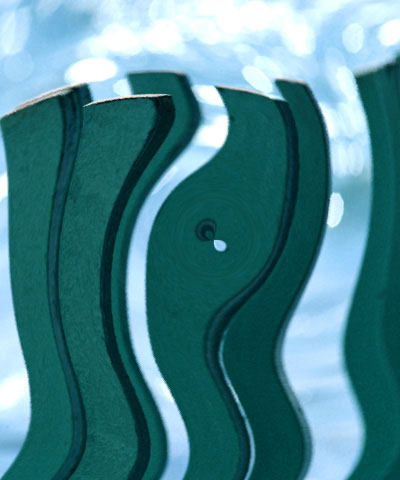
The Polar Displacement filter uses a Map Layer to displace pixels radially outward from the Center Point and angularly along an arc of a circle centered at the Center Point.
Function
Presets and Common Controls
BCC filters come with a library of factory installed presets plus the ability to create your own custom presets and preview them with the BCC FX Browser™.
BCC filters also include common controls that configure global effect preferences and other host-specific effect settings.
For more information about working with presets and other common controls, Click Here.
- Vegas Pro Workflow Tip: To use the Light Wrap feature in Vegas Pro you must apply the filter in Custom Composite Mode. For more information on working with Custom Composite Modes in Vegas, Click Here.
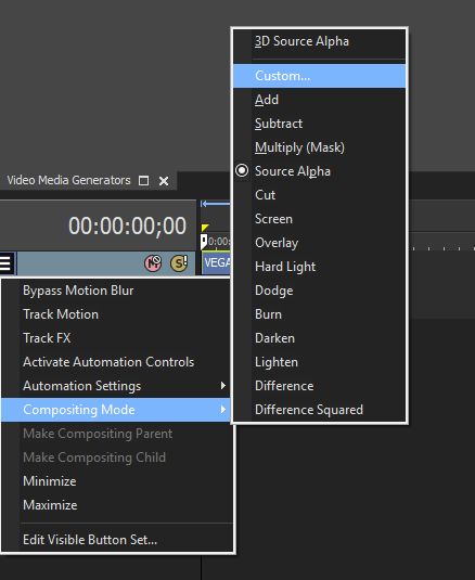 Using Custom Composites in Vegas Pro
Selecting the ProcessAlphaChannel Only checkbox allows you to distort the alpha channel without changing the underlying colors.
The Map menu determines which clip layer in the timeline is used to create the distortions in the source image.
- Note: If the Map Layer is partly transparent, the displacement amount is scaled by its alpha values. Pixels whose map alpha is 0 are not displaced.
Map Parameter Group
The Map parameters control the appearance of the map used to distort the source image.
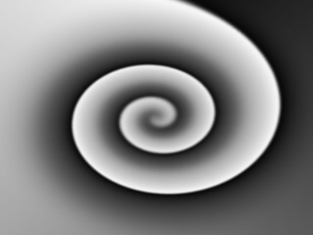
Pre Blur applies a blur to the Map Layer. Increasing Pre Blur can help eliminate sharp edges in the map to create a smoother effect.
 |
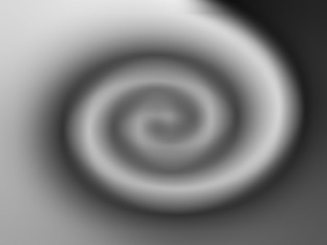 |
| Pre Blur=0 | Pre Blur=50 |
Displacement filters often look rough if the Map Layer is high-contrast or has sharp edges. Blur Threshold softens the Map Layer before computing the displacements. After the Map Layer is blurred, the blurred track is compared to the original Map Layer, and the color change for each channel is reduced by a relative amount. Increasing Blur Threshold blurs parts of the image with rapid changes in color without blurring subtle details. This is particularly appropriate for a displacement map, which can severely distort areas of the image where the Map Layer changes rapidly.
Map Black Level sets the channel values of the map that are output as pure black. All pixels whose value is lower than the Map Black Level value become pure black. For example, if Map Black Level is set to 50, all pixels with a value of 50 or less output to a value of 0. The remaining values (50-255) are remapped to produce a smooth gradient from black to white.
 |
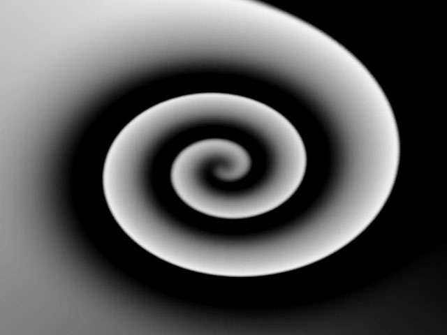 |
| Map Black Level=0 | Map Black Level=75 |
Map White Level sets the channel values of the input image that are treated as pure white by the filter. All pixels whose value is higher than the Map White Level value become to pure white. For example, if Map White Level is set to 200, all pixels with a value of 200 or more are output to a value of 255. The remaining values (0-200) are remapped to produce a smooth gradient from black to white.
 |
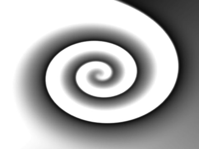 |
| Map White Level=255 | Map White Level=175 |
Map Gamma adjusts the midlevel gray values of the input image by adjusting the gamma. Increasing Map Gamma lightens the shadows and reduces contrast. Decreasing Gamma darkens the shadows and increases contrast.
The View Map checkbox allows you to view the Map Layer as you adjust it. Deselect this option before rendering.
The Master Displacement control defaults to 100 and scales all of the displacement amounts. Animating this controls allows you to animate the total displacement.
Center Point Parameter Group
Center Point sets the center point for the radial and angular displacements on the X and Y axis.
The Rad. Channel menu sets which channel in the Map Layer controls radial displacement. The choices are Red, Green, Blue, Luma, White, Gray, and Black. White treats all pixels as if they were white (i. e. fully displaces each pixel to the White Radial Displacement value). Gray treats all pixels as if they were 50% gray (resulting in no displacement). Black treats all pixels as if they were black, thereby displacing all pixels to the negative of the White Radial Displacement value.
Max. Radial Displacement sets the amount of radial displacement (in pixels) applied to pixels in the source image that correspond to white pixels in the Map Layer. The displacement for black pixels is the negative of this value.
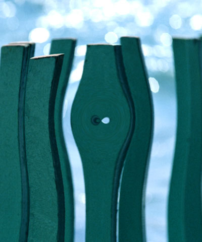 |
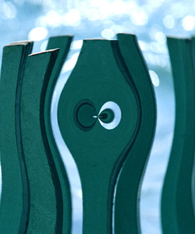 |
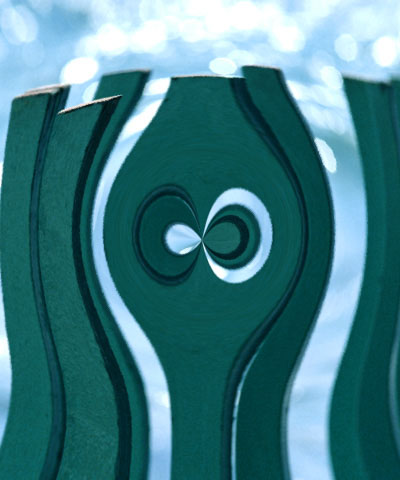 |
| Max. Radial Disp.=50 | Max. Radial Disp.=100 | Max. Radial Disp.=150 |
Radial Reference Level allows you to control the channel where the displacement occurs. If you want all of the displacement in the angular channel, set Radial Reference Level to 255. To have all the displacement occur Radially, set Radial Reference Level to 0.
Ang. Channel menu sets which channel in the Map Layer controls angular displacement. The choices are Red, Green, Blue, Luma, White, Gray, and Black. White treats all pixels as if they were white (i. e. fully displaces each pixel to the White Angular Displacement value). Gray treats all pixels as if they were 50% gray (resulting in no displacement). Black treats all pixels as if they were black, thereby displacing all pixels to the negative of the White Angular Displacement value.
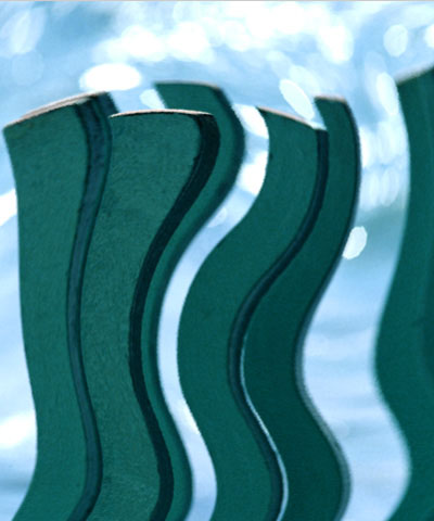
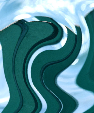
Max. Angular Displacement sets the number of degrees of angular displacement applied to pixels in the source image that correspond to white pixels in the Map layer. The displacement for black pixels is the negative of this value.
 |
 |
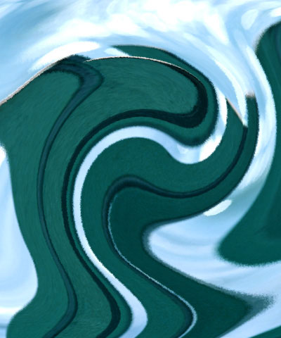 |
| Max. Angular Disp.=50 | Max. Angular Disp.=100 | Max. Angular Disp.=150 |
Ang. Reference Level allows you to control the channel where the displacement occurs. If you want all of the displacement in the radial channel, set Ang. Reference Level to 255. To have all the displacement occur angularly, set Ang. Reference Level to 0.
The Map Behavior menu determines how the map is applied when the source image is a different size than the image in the Map Layer. If your map is the same size as the image to which you are applying the filter, the Map Behavior settings all produce the same result.
- Center Map centers the map on the source and does not displace the source image outside the boundaries of the centered Map Layer.
- Stretch Map to Fit resizes the Map Layer to the size of the source.
- Tile Map creates tiles from the Map Layer and uses them to displace the source. Tile Map only has an effect when the map is smaller than the source image.
PixelChooser
The BCC PixelChooser provides simple, built-in masking of the effect result. The PixelChooser is generally used to select a portion of the image and restrict an effect to just the selected area while maintaining the original image content in unselected regions. The selection can be based on geometric shapes or on the image’s luma/color properties.
For more information on the PixelChooser, Click Here.
Distortion Pinning
The BCC Distortion Pinning controls are used to fine tune edge treatment in situations where a distortion effect might cause regions from outside the image edges to be remapped inside the boundary.
For more information on the BCC Distortion Pinning controls, Click Here.
